Frelander 2. Manual - part 301


  Index      Land Rover     Land Rover Frelander 2 - service repair manual 2006-2010 year


Search            


Content   ..  299  300  301  302   ..


Frelander 2. Manual - part 301


12

-

Restraints Control Module (RCM)

13

-

Knock sensors (2 off)

14

-

Fuel rail temperature/pressure sensor

15

-

Clockspring

16

-

Terrain response control module

17

-

Transmission Control Module (TCM)

18

-

ABS module

19

-

Diagnostic socket

20

-

CJB

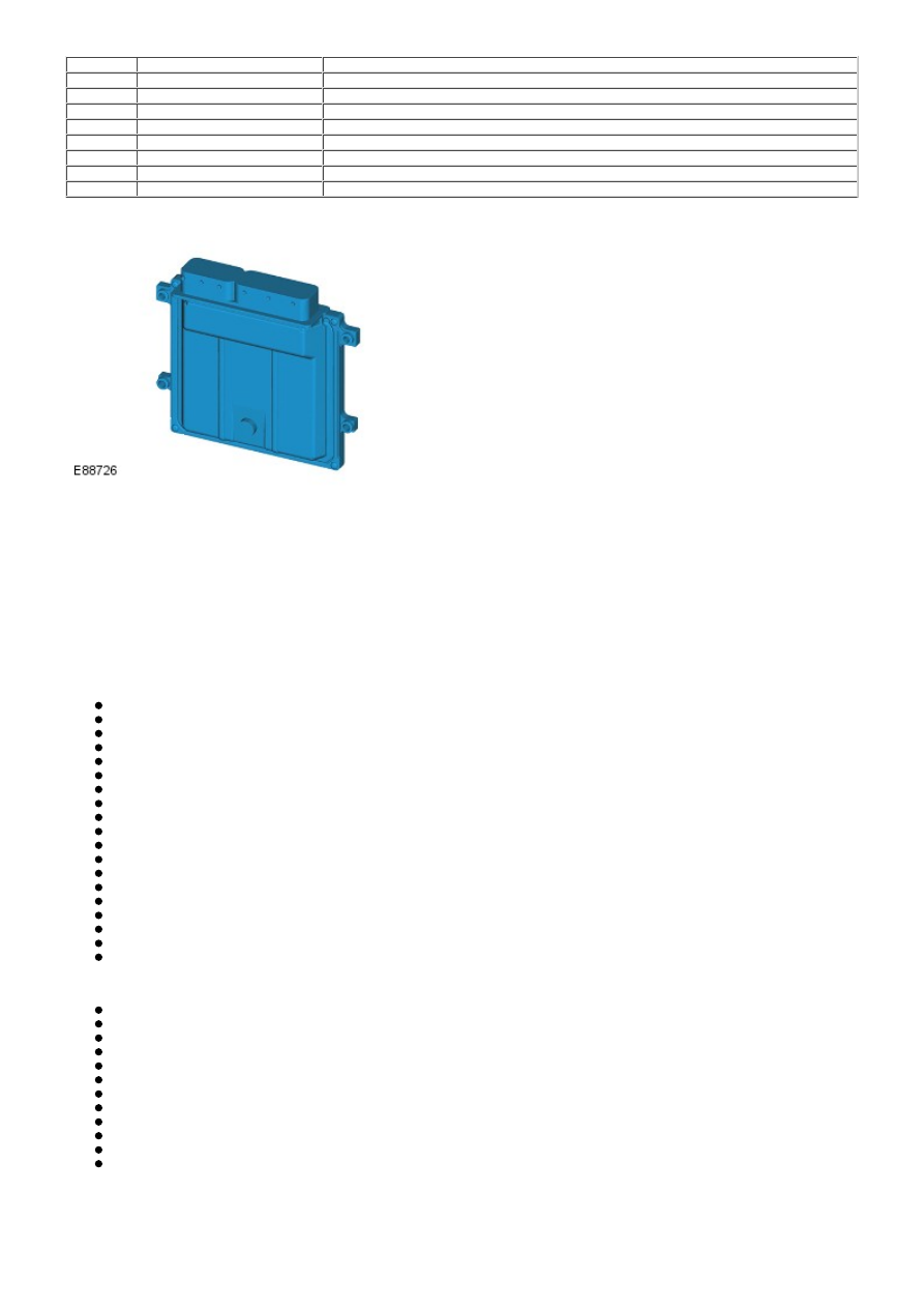
ENGINE CONTROL MODULE (ECM)

The ECM is located on a bracket in a central position on the engine compartment firewall. The ECM is attached to a
housing and secured with 4 screws. The housing is located in the bracket and locked in position.

The ECM is supplied with battery voltage from fuses located in the BJB. A permanent battery supply is provided to ensure
adaptive data is not lost when the engine is switched off.

A regulator, located within the ECM, supplies a 5V current to internal components such as the micro-processor unit. Other
components or functions requiring full battery voltage are controlled by external relays or internal power stages.

The micro-processor within the ECM receives signals from different components and control modules and uses a program
within the ECM software to interpret the signal information and issue signals which relate to how the engine components
and functions should be controlled.

The ECM receives inputs from the following:

CMP sensors
CKP sensor
Fuel rail pressure sensor
MAF sensor
Knock sensors
Fuel rail temperature/pressure sensor
ECT sensor
Engine oil level/temperature sensor
Manifold Absolute Pressure (MAP) sensor
Electric throttle - Throttle Position (TP) sensor
APP sensor
Fuel tank leakage monitoring module (NAS only)
Cooling fan control
Heated Oxygen sensors (HO2S)
Stop lamp switch (via Central Junction Box (CJB))
Speed control inhibit switch
Intake Air Temperature (IAT) sensor
Ambient Air Temperature (AAT) sensor
Transmission Control Module (TCM).

The ECM sends outputs to the following:

Main relay
Air Conditioning (A/C) relay
Fuel injectors
Ignition coils
Engine cooling fan control
Electric throttle
Electric fuel pump driver module
Variable Camshaft Timing (VCT) solenoids
Starter relay control
Variable intake manifold control valves
Variable inlet cam profile switching solenoid valves
Transmission Control Module (TCM).

SENSORS

The ECM optimizes engine performance by interpreting signals from numerous vehicle sensors and other inputs. Some of
these signals are produced by the actions of the driver, some are supplied by sensors located on and around the engine

and some are supplied by other vehicle systems.

Camshaft Position (CMP) Sensor

Two CMP sensors are located in the camshaft housing at the Left Hand (LH) end of the engine. The sensors are located in
a hole in the housing and are secured with a screw. There is a CMP sensor for each camshaft.

The CMP sensors monitor the position of the camshafts to establish ignition timing order, fuel injection triggering and for
accurate Variable Camshaft Timing (VCT) operation. The ECM can also use the CMP sensors to determine which cylinder
has a misfire or knock using the CMP signal output.

The CMP sensor is a Hall-effect sensor which switches a 5V supply from the ECM on and off. The supply is switched when
teeth machined onto a pulse wheel on the camshaft pass by the tip of the sensor. The teeth are of differing shapes, so
the ECM can determine the exact position of the camshaft at any time. W hen one of the teeth passes by the sensor tip, a
signal is transmitted to the ECM which can vary between 0 and 5V. The signal is high when a tooth is directly adjacent to
the sensor and is low when the tooth is away from the sensor.

Failure of one or both of the sensors will result in the ECM using a default map for ignition timing and knock control will be
disabled.

The ECM monitors the sensor for correct function and can diagnose and store fault codes for sensor faults. These can be
retrieved using a Land Rover approved diagnostic system.

Crankshaft Position (CKP) Sensor

The CKP sensor is located on the forward side of the transmission torque converter housing, in line with the engine
flywheel. The sensor is secured with a bolt into a bracket attached to the gear housing. A reluctor ring is fitted to the
outer diameter of the crankshaft flexplate and the sensor reacts to the gaps in the reluctor ring to determine engine speed
and position information. The sensor has 2 wires from the ECM sensor ground and a feedback signal.

The CKP sensor is an inductive type sensor which produces a sinusoidal output voltage signal. This voltage is induced by
the proximity of the moving reluctor ring gaps, which excite the magnetic flux around the tip of the sensor when each gap
passes. This output voltage will increase in magnitude and frequency as the engine speed rises determined by an increase
in the speed at which the gaps on the reluctor ring pass the sensor. The signal voltage can be as low as 0.1V at low
engine speeds and up to 100V at high engine speeds. The ECM does not react to the output voltage (unless the voltage is
extremely low or high), instead it measures the time intervals between each pulse (signal frequency). The signal is
determined by the number of gaps passing the sensor, and the speed at which they pass. The reluctor ring has 2 gaps
missing to give the ECM a synchronization point and determine the position of the crankshaft. The CKP sensor signal is
also used for misfire detection.

The signal produced by the CKP sensor is critical to engine running. Failure of the sensor when the engine is running will
result in the engine stopping immediately. The engine can be restarted using signals from the CMP sensors but the engine
speed will be limited to 3000 rpm and the Malfunction Indicator Lamp (MIL) will be illuminated.

The ECM monitors the sensor for correct function and can diagnose and store fault codes for sensor faults. These can be
retrieved using a Land Rover approved diagnostic system.

Fuel Rail Pressure/Temperature Sensor

The fuel rail pressure/temperature sensor is located on the LH end of the fuel rail. The ECM supplies the combined
pressure and temperature sensor with a 5V reference voltage and a ground and measures the returned signals for pressure
and temperature.

Fuel pressure

The fuel pressure sensor is a peizo resistor type sensor. The sensor receives a 5V reference voltage from the ECM and
produces an analogue signal of between 0 and 5V depending on the pressure sensed. Low pressure gives a low voltage
output and consequently high pressure gives a higher voltage output. The ECM uses this pressure signal to adjust the fuel
pump module output pressure by sending controlling signals to the FPDM and for injector timing.

The ECM monitors the fuel pressure sensor for faults and can store fault related codes. These can be retrieved using a
Land Rover approved diagnostic system. Sensor operation can also be checked using a Land Rover approved diagnostic
system to check fuel pressure. If no fuel pressure is in the fuel rail, the sensor will read and output atmospheric pressure.

Fuel Temperature

The fuel temperature sensor is a Negative Temperature Co-efficient (NTC) sensor. The sensing thermistor element
resistance decreases as the sensor temperature increases. The ECM supplies the sensor with a 5V reference voltage and a
ground and measures the returned signal as a temperature.

The resistance in the sensor changes with fuel temperature. A low fuel temperature will result in a high voltage being
returned to the ECM and high fuel temperature will return a low voltage reading of between 0 - 5V.

The ECM monitors the fuel temperature sensor for faults and can store fault related codes. These can be retrieved using a
Land Rover approved diagnostic system. The ECM uses the ECT temperature signal as a default but only up to a maximum
of 100°C (212°F).

Mass Air Flow (MAF)/Intake Air Temperature (IAT) Sensor

The MAF/IAT sensor is located in the outlet pipe from the air cleaner housing. The combined MAF/IAT functions are
connected to the ECM on separate wires. The sensor has an extended moulding which is located in a central position in the
air flow through the air cleaner housing outlet pipe, through which the air flow and temperature are measured.

Mass Air Flow (MAF) Sensor

The MAF sensor measures the mass of air being drawn into the engine. The air mass is calculated by the cooling effect of
inlet air passing over a 'hot film' element contained within the sensor. The higher the air flow, the greater the cooling
effect on the element which in turn lowers the electrical resistance of the 'hot film' element. The ECM uses this resistance
value to calculate the air mass or volume of air flowing into the engine.

The MAF sensor receives a battery voltage supply via the ECM and the main relay. The ECM provides a ground and a signal
path for the resistance signal from the 'hot film' sensor. The analogue signal from the MAF sensor varies between 0.5 and
5V. Low air flow gives a low voltage and high air flow gives a high voltage.

The MAF signal is used by the ECM to determine:

the correct fuel quantity (injection period) to maintain the correct air/fuel ratio required for correct operation of the
engine and the catalysts

the ignition timing
the engine load.

The ECM monitors the MAF sensor for faults and can store fault related codes. These can be retrieved using a Land Rover
approved diagnostic system.

Intake Air Temperature (IAT) Sensor

The IAT sensor measures the temperature of the intake air entering the engine. The sensor is a temperature dependant
resistor (thermistor). The thermistor is a NTC sensor element. The element resistance decreases as the sensor
temperature increases. The ECM supplies the sensor with a 5V reference voltage and a ground and measures the returned
signal as a temperature.

The resistance in the sensor changes with intake air temperature. A low intake air temperature will result in a high voltage
being returned to the ECM and high intake air temperature will return a low voltage reading of between 0 - 5V.

The ECM monitors the IAT sensor for faults and can store fault related codes. These can be retrieved using a Land Rover
approved diagnostic system. If the IAT sensor fails, the ECM uses a default temperature value using the fuel rail
pressure/temperature sensor.

Knock Sensors

Two knock sensors are located on the front of the engine and are each secured to threaded holes in the engine cylinder
block with a bolt. The knock sensors are used by the ECM to monitor combustion knocking or vibration generated by
ignition combustion. The knock sensors are each connected to the ECM via a twisted pair of wires which reduces electrical
interference disrupting the signal produced.

Each knock sensor contains a peizo-ceramic crystal which produces a voltage when an external force applies pressure or
load on it. When the engine is running, compression waves produced by the combustion process, creates pressure waves
which pass through the engine cylinder block. These pressure waves are detected by the knock sensors and the deflection
of the crystal caused by the pressure waves causes the sensors to produce an output signal. The signals are passed to the
ECM which compares them with stored mapped signals in its memory.

The ECM can then determine when the correct combustion occurs in individual cylinders. If incorrect combustion detonation
is detected, the ECM can retard the ignition timing on that cylinder for a number of combustion cycles. The ignition timing
will be gradually returned to its optimal settings. If the knock is still detected the ECM will increase the injection period,
which has a cooling effect on that cylinder.

The signals from the knock sensors are used in conjunction with the CMP sensors and the CKP sensor to determine the
ignition cycle and therefore identify which cylinder is knocking. The ECM is programmed to use ignition maps based on high
quality 95-98 RON fuel. If fuel of a poor quality such as 91 RON is used the engine may suffer from knock (pinking) for a
period of time. The ECM is capable of learning and adapting to the low grade fuel and will modify its internal ignition
mapping to compensate for the low grade fuel. This feature of the ECM is called adaption.

If one or both knock sensors fail or the signal becomes implausible, the ECM will cancel closed loop control of the ignition
system. The ECM will use a default 'safe' ignition map to ensure the pre-detonation does not damage the engine by
setting maximum retard control on spark advance. The driver may notice 'pinking' under certain driving conditions and a
loss of performance. The ECM monitors the knock sensors for faults and can store fault related codes. These can be
retrieved using a Land Rover approved diagnostic system.

Engine Coolant Temperature (ECT) Sensor


Content   ..  299  300  301  302   ..