Frelander 2. Manual - part 247


  Index      Land Rover     Land Rover Frelander 2 - service repair manual 2006-2010 year


Search            


Content   ..  245  246  247  248   ..


Frelander 2. Manual - part 247


Remove the throttle body.

6.

Remove and discard the gasket.

7.

Installation

Clean the component mating faces.

1.

Install a new gasket.

2.

3. 

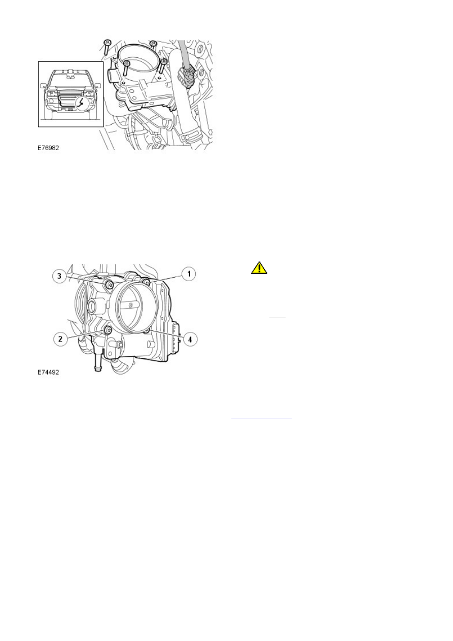
CAUTION: Make sure that the mating faces are

clean and free of foreign material.

Install the throttle body and tighten the screws in the
sequence shown.

Torque: 8 Nm

3.

Install the engine undershield.

Refer to: 

Engine Undershield

 (501-02 Front End Body Panels,

Removal and Installation).

4.

Install the front undershield.

5.

Install the front towing eye cover.

6.

Fuel Charging and Controls - I6 3.2L Petrol - Fuel Injector

Removal and Installation

Removal

• NOTE: The process to remove a fuel injector is shown the the Fuel Rail procedure.

Remove the fuel injector.

Refer to: 

Fuel Rail

 (303-04A Fuel Charging and Controls - I6 3.2L

Petrol, Removal and Installation).

1.

Installation

Install the fuel injector.

Refer to: 

Fuel Rail

 (303-04A Fuel Charging and Controls - I6 3.2L

Petrol, Removal and Installation).

1.

Fuel Charging and Controls - I6 3.2L Petrol - Fuel Rail

Removal and Installation

Removal

WARNING: Wait for a minimum of 1 minute after the engine has stopped before carrying out any repair to the fuel

injection system.

Remove the cover and disconnect the battery ground cable.

Refer to: 

Specifications

 (414-00 Battery and Charging System -

General Information, Specifications).

1.

Remove the engine cover.

Refer to: 

Engine Cover - I6 3.2L Petrol

 (501-05 Interior Trim and

Ornamentation, Removal and Installation).

2.

3. WARNINGS:

 Avoid flames, sparks or lighted substances.

 Be prepared to collect escaping fuel.

Release the fuel pressure.

3.

4.

5. CAUTIONS:

 Extreme cleanliness must be exercised when

handling these components.

 Make sure that all openings are sealed.

5.

6. NOTE: Do not remove the fuel injectors, if the rail is
being removed for access.

6.

7. 

CAUTION: A new O-ring seal is to be installed.

7.

8. 

CAUTION: Cap the fuel injector nozzle to

prevent damage before storing vertically.

• NOTE: Do not disassemble further if the component is
removed for access only.

• NOTE: If the fuel injectors are not being removed
from the fuel rail only the lower O-ring seals will need
to be renewed.

Remove and discard the fuel injector O-ring seals.

8.

9.


Content   ..  245  246  247  248   ..