Frelander 2. Manual - part 228
Item
Part Number
Description
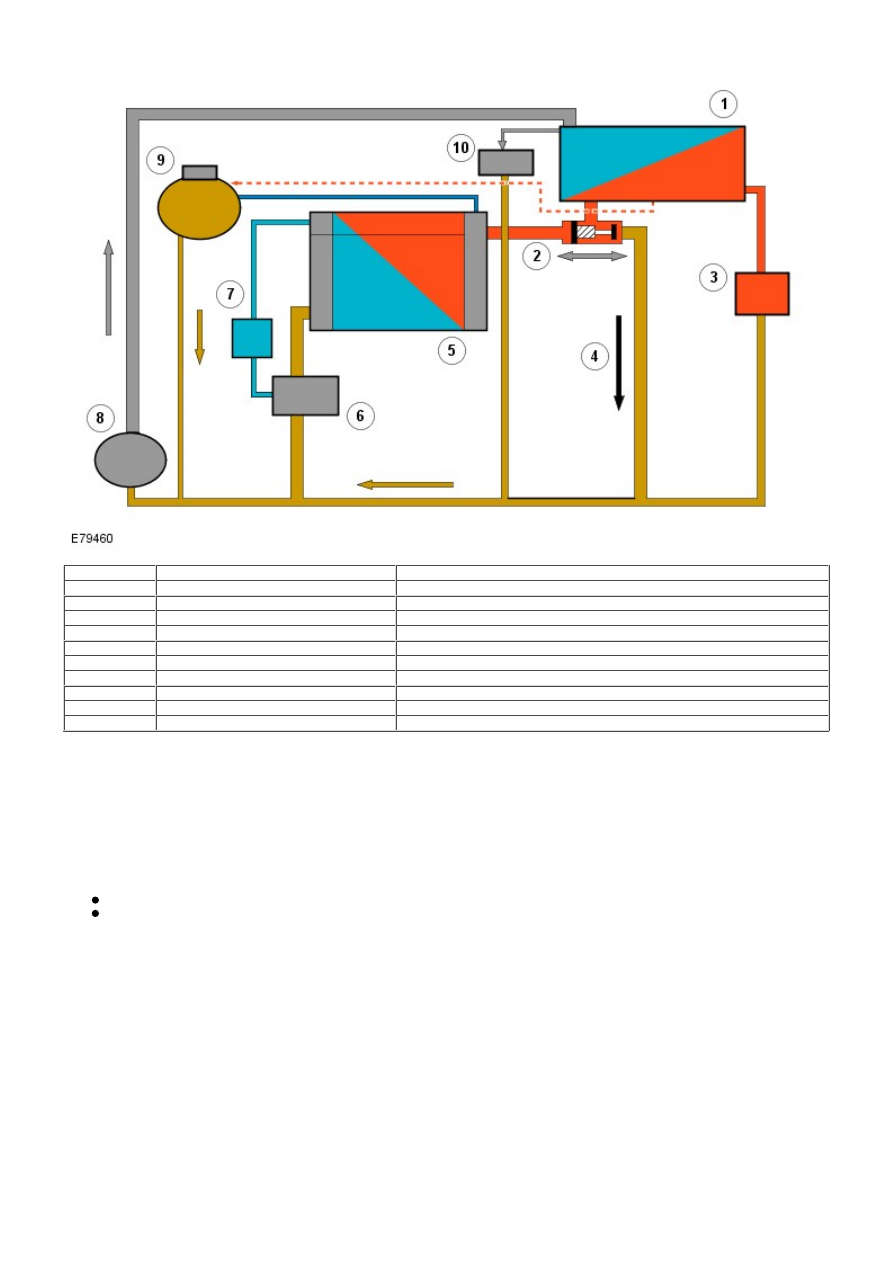
1
-
Engine
2
-
Thermostat
3
-
Cabin heater core
4
-
By-pass
5
-
Radiator
6
-
Venturi exit
7
-
Transmission oil cooler
8
-
Coolant pump
9
-
Coolant expansion tank
10
-
Engine oil cooler
PRINCIPLES OF OPERATION
At idle, and low outdoor temperatures (lower than -10°C (14°F)) the engine's idle speed increases from approximately 650
rpm to approximately 750 rpm. This is to increase the coolant flow through the passenger compartment element, which, in
turn, makes it possible to increase the heat in the passenger compartment. The coolant pump is driven by the power
steering pump through a flange.
Coolant Flow - Closed Thermostat
Coolant leaves the engine block via the 2 circuits at the rear edge on the intake side of the engine.
The coolant is routed from one of the circuits to the engine's oil cooler and onwards to the coolant pump.
Coolant is routed from the other circuit to a 'by-pass' circuit where there is a valve. The valve is closed at engine
speeds up to approximately 1500 rpm. At approximately 1500 rpm, the valve opens and coolant passes through the
circuit. By keeping the valve closed at low engine speeds, a sufficient flow is guaranteed through the passenger
compartment element to obtain a good climate (sufficient heat) in the passenger compartment.