Freelander 1. Manual - part 186


  Index      Land Rover     Freelander 1 - service manual 2002 year


Search            


Content   ..  184  185  186  187   ..


Freelander 1. Manual - part 186


REAR SUSPENSION

REPAIRS

64-7

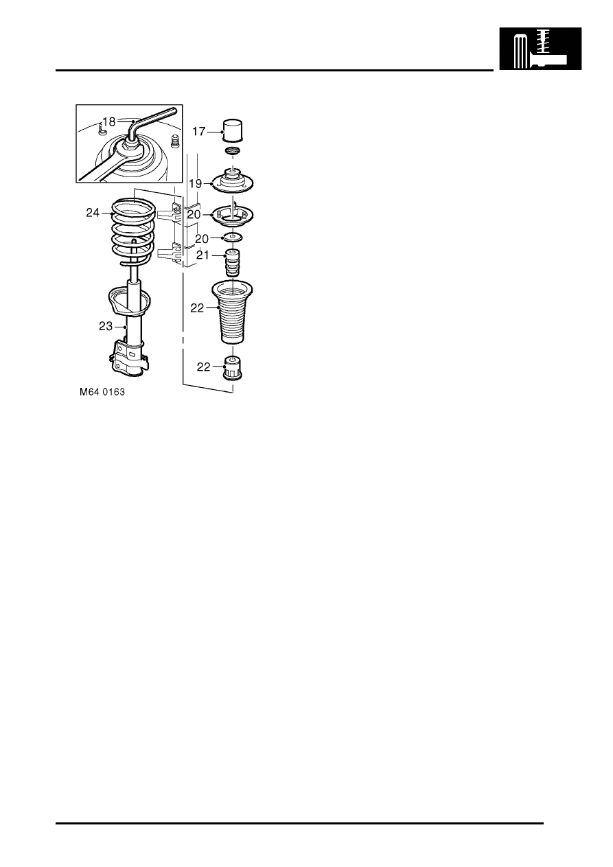
17. Remove cover from  top mounting.
18. Compress spring by 2 to 3 cm until loose, hold 

damper shaft with Allen key, remove and 
discard mounting plate nut.

19. Remove top mounting plate.
20. Remove rebound washer and mounting plate.
21. Remove spring aid and bump plate.
22. Remove spring seat, dust cover and bump stop 

cup.

23. Remove damper from spring.
24. Release and remove spring from compressor.

Refit

1. Inspect damper, spring mounting rubbers and 

bearing for deterioration and damage.

2. Clean mating faces of spring, mounting and 

mounting plate.

3. Clean damper shaft and bump stop plate.
4. Position spring and damper assembly to spring 

compressor. Compress spring. 

5. Fit damper to spring, ensure spring locates in 

cut recess in damper plate.

6. Fit bump stop, bump stop cup and dust cover to 

damper.

7. Fit spring aid and bump plate.
8. Fit mounting plate and rebound washer.
9. Using new nut, hold damper shaft with Allen 

key and tighten nut to 57 Nm (42 lbf.ft).

CAUTION: Note alignment of top mounting, 
spring and damper dust cover.

10. Fit top mounting cover.
11. Release and remove spring from compressor.
12. Clean mating face of top mounting plate.
13. Fit rubber seal to top mounting.
14. Position damper assembly and align top 

mounting to body, fit nuts and tighten to 45 Nm 
(33 lbf.ft).

15. Fit rear quarter lower trim casings.


 + 

 INTERIOR TRIM COMPONENTS, 

REPAIRS, Trim casing - rear quarter - lower 
- 3 door.
 

 + 

 INTERIOR TRIM COMPONENTS, 

REPAIRS, Trim casing - rear quarter - lower 
- 5 door.

16. Fit hub to damper and tighten bolts to 205 Nm 

(151 lbf.ft).

17. Clean ABS sensor, smear sensor with an anti-

seize grease and fit sensor to hub.

CAUTION: Ensure ABS sensor is fully 
located into hub, so that sensor touches 
pole wheel teeth.

18. Secure brake hose and ABS sensor harness to 

damper.

19. Secure brake hose  with 'C' clip.
20. Remove plugs and clean brake pipe male end.
21. Align hose to brake pipe and tighten union to 14 

Nm (10 lbf.ft). 

22. Remove clamp from brake hose.
23. Bleed brake system.


 + 

 BRAKES, ADJUSTMENTS, Brake 

bleed.

24. Fit road wheel(s) and tighten nuts to 115 Nm 

(85 lbf.ft).

25. Remove stands and lower vehicle.

REAR SUSPENSION

64-8

REPAIRS

Trailing arm 

$% 64.35.46

Remove

1. Raise rear of vehicle.

WARNING: Do not work on or under a 
vehicle supported only by a jack. Always 
support the vehicle on safety stands.

2. Remove road wheel.

3. Remove nut and bolt securing trailing link to 

hub.

4. Remove bolt securing trailing link to bracket.
5. Remove trailing link.

Refit

1. Fit trailing link.
2. Fit bolt to bracket but do not tighten at this 

stage.

3. Align trailing link to hub, fit nut and bolt but do 

not tighten at this stage.

4. Support weight of vehicle with jack under rear 

hub.

CAUTION: Nuts and bolts must be tightened 
with weight of vehicle on suspension.

5. Tighten nuts and bolts to 120 Nm (89 lbf.ft). 
6. Fit road wheel(s) and tighten nuts to 115  Nm 

(85 lbf.ft).

7. Remove stands and lower vehicle.
8. Check and if necessary adjust rear wheel 

alignment.

Bush - trailing arm 

$% 64.35.48

Remove

1. Remove trailing arm.


 + 

 REAR SUSPENSION, REPAIRS, 

Trailing arm.

2. Note and mark bush orientation to trailing arm.

3. Using LRT-64-023  remove trailing arm bush.

Refit

1. Ensure bush bore is clean.
2. Ensure bush is correctly aligned.

REAR SUSPENSION

REPAIRS

64-9

3. Using LRT-64-023  fit new bush.
4. Fit trailing arm.


 + 

 REAR SUSPENSION, REPAIRS, 

Trailing arm.

Link - adjustable - transverse 

$% 64.35.70

Remove

1. Raise rear of vehicle.

WARNING: Do not work on or under a 
vehicle supported only by a jack. Always 
support the vehicle on safety stands.

2. Remove road wheel.

3. Remove nut, bolt and washers securing 

transverse links to hub.

4. Remove nut and bolt securing adjustable 

transverse link to subframe. Collect dynamic 
damper.

5. Remove transverse link.

Refit

1. Fit transverse link.
2. Fit nuts, bolts, dynamic damper and washers 

securing transverse link to hub and subframe 
but do not tighten at this stage.

NOTE: Ensure that washers are fitted to both 
ends of bolts

3. Support weight of vehicle with jack under rear 

hub.

CAUTION: Nuts and bolts must be tightened 
with weight of vehicle on suspension.

4. Tighten nuts and bolts to 105 Nm (77 lbf.ft). 
5. Fit road wheel(s) and tighten nuts to 115  Nm 

(85 lbf.ft).

6. Remove stands and lower vehicle.
7. Check and if necessary adjust rear wheel 

alignment.

REAR SUSPENSION

64-10

REPAIRS

Link - transverse fixed 

$% 64.35.72

Remove

1. Raise rear of vehicle.

WARNING: Do not work on or under a 
vehicle supported only by a jack. Always 
support the vehicle on safety stands.

2. Remove road wheel.

3. Remove nut and bolt securing transverse link to 

hub.

4. Remove nut and bolt securing fixed transverse 

link to subframe.

5. Remove transverse link.

Refit

1. Fit transverse link.
2. Fit nuts, bolts and washers securing transverse 

link to hub and subframe but do not tighten at 
this stage.

3. Support weight of vehicle with jack under rear 

hub.

CAUTION: Nuts and bolts must be tightened 
with the weight of the vehicle on the 
suspension.

4. Tighten nuts and bolts to 105 Nm (77 lbf.ft). 
5. Fit road wheel(s) and tighten nuts to 115  Nm 

(85 lbf.ft).

6. Remove stands and lower vehicle.
7. Check and if necessary adjust rear wheel 

alignment.

Bush - link - transverse 

$% 64.35.76

Remove

1. Remove transverse link.


 + 

 REAR SUSPENSION, REPAIRS, Link 

- transverse fixed.

2. Note and mark bush orientation.

3. Large bush: Use LRT-60-008 to remove bush.


Content   ..  184  185  186  187   ..