Freelander 1. Manual - part 183


  Index      Land Rover     Freelander 1 - service manual 2002 year


Search            


Content   ..  181  182  183  184   ..


Freelander 1. Manual - part 183


FRONT SUSPENSION

REPAIRS

60-11

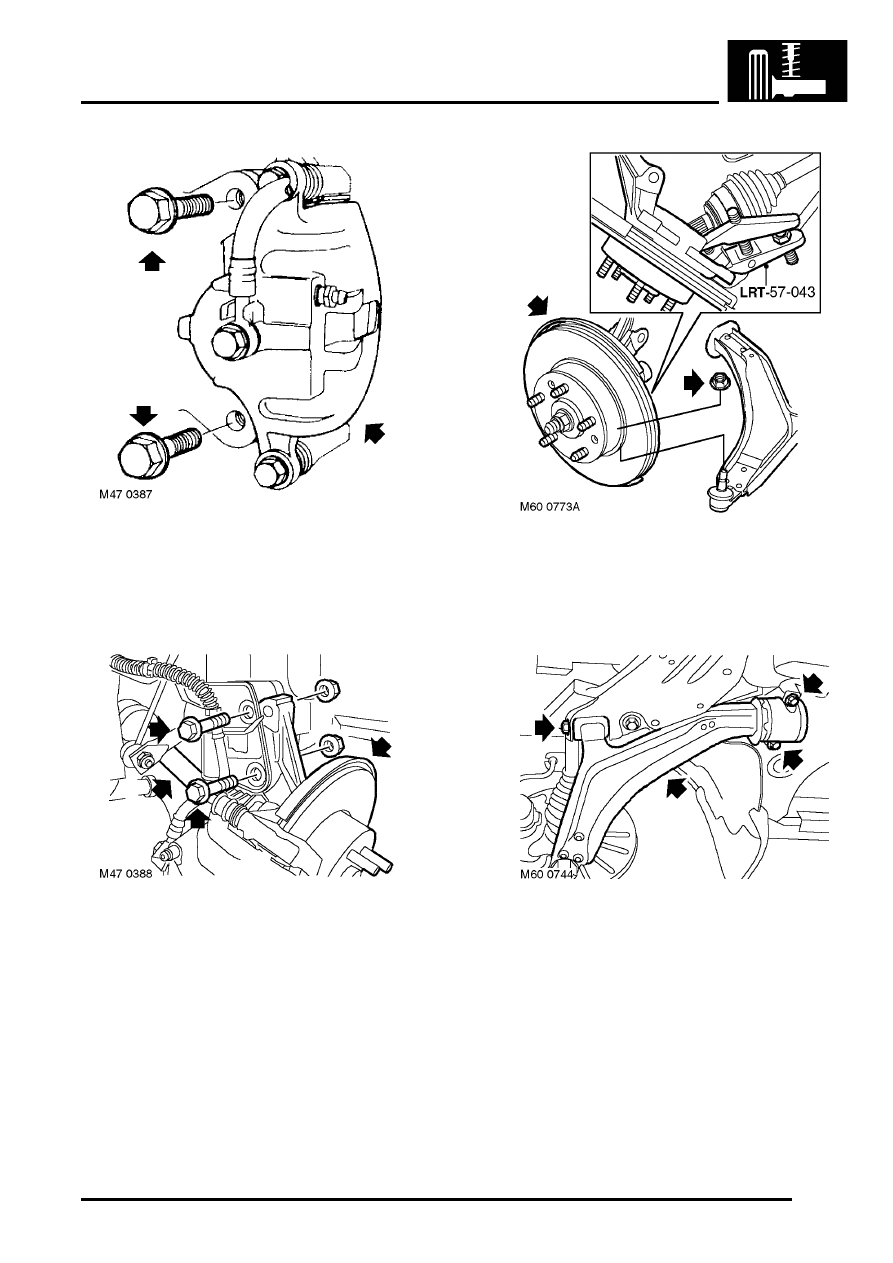
9. Remove 2 bolts securing brake caliper to hub. 

Release caliper from hub and tie aside.

CAUTION: Do not allow caliper to hang on 
brake hose.

10. Remove 2 nuts and bolts securing hub to 

damper.

11. Release drive shaft from hub.
12. Tie drive shaft aside.

13. Remove nut securing lower arm ball joint. 

discard nut.

14. Break taper joint using  LRT-57-043.
15. Remove hub assembly.

16. Remove 2 bolts securing lower arm rear bush 

housing.

17. Remove bolt securing lower arm front 

mounting.

18. Remove lower arm.

FRONT SUSPENSION

60-12

REPAIRS

19. Remove nut from rear mounting, remove 

snubber washer and remove mounting.

CAUTION: Note orientation of snubber 
washer.

Refit

1. Clean rear mounting mating faces.
2. Fit rear mounting and snubber rubber to lower 

arm, fit nut but do not tighten at this stage.

CAUTION: Ensure correct orientation of 
snubber washer. Ensure that 'OUT' is 
visible on snubber washer when fitted.

3. Position lower arm and align to subframe fit bolt 

but do not tighten at this stage.

4. Clean hub to lower arm ball joint mating faces.
5. Fit hub assembly  to lower joint, fit new nut and 

tighten to 65 Nm (48 lbf.ft).

6. Clean drive shaft and flange splines.
7. Fit drive shaft to hub.
8. Fit new hub nut but do not tighten at this stage.
9. Fit hub to damper, fit nuts and bolts and tighten 

to 205 Nm (151 lbf.ft). 

10. Position caliper to brake disc fit bolts and 

tighten to 100 Nm (74 lbf.ft).

11. Fit brake hose to bracket on damper and 

secure with clip.

12. Clean ABS sensor, smear sensor with an anti-

seize grease and fit sensor to hub.

CAUTION: Ensure ABS sensor is fully 
located into hub, so that sensor touches 
pole wheel teeth.

13. Fit ABS sensor lead to bracket.
14. Tighten lower arm front bush bolts to 190 Nm 

(140 lbf.ft).

CAUTION: Nuts and bolts must be tightened 
with weight of vehicle on suspension.

15. Align bush housings ensuring roll pin is 

correctly located. Fit bolts and tighten to 105 
Nm (77 lbf.ft).

16. Tighten rear bush housing nut to 140 Nm (103 

lbf.ft).

17. Fit new drive shaft nut and  tighten to 400 Nm 

(295 lbf.ft). Stake nut to shaft. 

18. Fit underbelly panel.


 + 

 EXTERIOR FITTINGS, REPAIRS, 

Panel - underbelly.

19. Fit road wheel(s) and tighten nuts to 115 Nm 

(85 lbf.ft).

20. Remove stands and lower vehicle.

FRONT SUSPENSION

REPAIRS

60-13

Rear beam 

$% 60.35.23

Remove

1. Remove underbelly panel.


 + 

 EXTERIOR FITTINGS, REPAIRS, 

Panel - underbelly.

2. Remove bolt securing engine lower steady to 

beam.

3. Remove 4 bolts securing anti-roll bar saddle 

clamps to beam.

4. Support anti-roll bar.

5. Loosen nuts securing lower arm rear 

mountings.

6. Remove 2 bolts securing each lower arm rear 

bush housing.

7. Remove lower arm pivot bush bolts.
8. Release lower arms from beam.

9. Support beam and remove 2 remaining bolts 

securing beam.

10. Lower and remove beam.

FRONT SUSPENSION

60-14

REPAIRS

Refit

1. Position and align beam, fit new bolts securing 

beam to body but do not fully tighten at this 
stage.

2. Locate lower arm bushes, fit but do not fully 

tighten bolts.

CAUTION: Nuts and bolts must be tightened 
with weight of vehicle on suspension.

3. Clean bush housing and mating faces on 

beam.

4. Align bush housings ensuring roll pin is 

correctly located. Fit bolts and tighten to 105 
Nm (77 lbf.ft).

5. Tighten bolts securing beam to body to 190 Nm 

(140 lbf.ft).

6. Fit saddle clamp bolts and tighten to 23 Nm (17 

lbf.ft).

7. Align engine lower steady, fit bolt and tighten to 

100 Nm (74 lbf.ft).

8. Lower vehicle.
9. Tighten lower arm front bush bolts to 190 Nm 

(140 lbf.ft).

10. Tighten lower arm rear bush nuts to 140 Nm 

103 lbf.ft).

11. Fit underbelly panel.


 + 

 EXTERIOR FITTINGS, REPAIRS, 

Panel - underbelly.

Bush - lower arm - front

$% 60.35.24

Remove

1. Remove underbelly panel.


 + 

 EXTERIOR FITTINGS, REPAIRS, 

Panel - underbelly.

2. Raise front of vehicle.

WARNING: Do not work on or under a 
vehicle supported only by a jack. Always 
support the vehicle on safety stands.

3. Remove 2 bolts securing rear bush housing to 

rear beam.

4. Release rear bush housing from body dowel.
5. Remove bolt securing lower arm front 

mounting.

6. Release lower arm front mounting from rear 

beam.

7. Using LRT-60-008 and adaptors remove lower 

arm bush.


Content   ..  181  182  183  184   ..