Freelander 1. Manual - part 169


  Index      Land Rover     Freelander 1 - service manual 2002 year


Search            


Content   ..  167  168  169  170   ..


Freelander 1. Manual - part 169


DRIVESHAFTS

REPAIRS

47-7

10. With  assistance pull hub assembly outwards 

and release drive shaft outer joint from hub 
assembly.

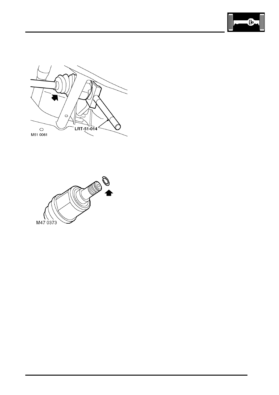
11. Taking care not to damage 'Flinger', release 

drive shaft inner joint from differential using 
LRT-51-014  and remove drive shaft.

12. Remove and discard drive shaft circlip.

Refit

1. Inspect differential seal,  renew if worn  or 

damaged.

2. Clean ends of drive shaft and locations in hub 

and differential.

3. Lubricate oil seal running surface with 

transmission oil.

4. Fit new circlip to drive shaft.
5. Fit drive shaft to differential and push fully 

home.

CAUTION: Pull the drive shaft to ensure the 
circlip is fully engaged and retains the shaft.

6. With assistance fit drive shaft to hub.
7. Fit new drive shaft nut but do not tighten at this 

stage.

8. Fit nut, bolt and dynamic damper to adjustable 

transverse link and tighten to 120 Nm (89 lbf.ft).

CAUTION: Nuts and bolts must be tightened 
with the weight of the vehicle on the 
suspension.

9. Fit nut and bolt to fixed transverse link and 

tighten to 120 Nm (89 lbf.ft).

10. Fit spacer, nut and bolt to trailing link and 

tighten to 120 Nm (89 lbf.ft).

11. Fit new drive shaft nut and  tighten to 400 Nm 

(295 lbf.ft). Stake nut to shaft. 

12. Check and top up oil level. 


 + 

 MAINTENANCE, MAINTENANCE, 

Rear Axle.

13. Fit road wheel(s) and tighten nuts to 115 Nm 85 

lbf.ft).

14. Remove stands and lower vehicle.
15. Connect battery earth lead.

DRIVESHAFTS

47-8

REPAIRS

Gaiter - outer - rear

$% 47.11.03

Remove

1. Disconnect battery earth lead.
2. Raise rear of vehicle.

WARNING: Do not work on or under a 
vehicle supported only by a jack. Always 
support the vehicle on safety stands.

3. Remove road wheel.
4. Remove drive shaft outer joint.


 + 

 DRIVESHAFTS, REPAIRS, Bell & 

joint - outer - rear.

5. Slide gaiter from shaft.

Refit

1. Clean drive shaft and gaiter.
2. Apply grease from the sachet to the joint.
3. Fit new gaiter to shaft.
4. Fit drive shaft outer joint. 


 + 

 DRIVESHAFTS, REPAIRS, Bell & 

joint - outer - rear.

5. Fit road wheel(s) and tighten nuts to 115 Nm 

(85 lbf.ft).

6. Remove stands and lower vehicle.
7. Connect battery earth lead.

Bell & joint - outer - rear

$% 47.11.04

Remove

1. Disconnect battery earth lead.
2. Raise rear of vehicle.

WARNING: Do not work on or under a 
vehicle supported only by a jack. Always 
support the vehicle on safety stands.

3. Remove road wheel.
4. Remove drive shaft.


 + 

 DRIVESHAFTS, REPAIRS, Shaft 

with both joints - rear.

5. Place drive shaft in vice.
6. Release both gaiter clips and discard. 

7. Slide gaiter along shaft to gain access to outer 

joint.

8. Using a suitable drift against the inner part of 

the joint, remove joint from shaft.

9. Inspect gaiter for damage and renew if 

necessary.

10. Remove and discard circlip from  drive shaft.

Refit

1. Clean drive shaft and gaiter.
2. Fit new circlip to drive shaft.
3. Position outer joint to shaft, use a screwdriver 

to press circlip into its groove and push joint 
fully onto shaft.

4. Apply grease from the sachet to the joint.
5. Position gaiter to joint and use a 'Band-it 

thriftool' LRT-99-019 to secure the 2 new clips.       

6. Fit drive shaft.


 + 

 DRIVESHAFTS, REPAIRS, Shaft 

with both joints - rear.

7. Fit road wheel(s) and tighten nuts to 115 Nm 

(85 lbf.ft).

8. Remove stands and lower vehicle.
9. Connect battery earth lead.

DRIVESHAFTS

REPAIRS

47-9

Gaiter - inner joint - rear

$% 47.11.16

Remove

1. Disconnect battery earth lead.
2. Raise rear of vehicle.

WARNING: Do not work on or under a 
vehicle supported only by a jack. Always 
support the vehicle on safety stands.

3. Remove road wheel.
4. Remove outer gaiter.


 + 

 DRIVESHAFTS, REPAIRS, Gaiter - 

outer - rear.

5. Release both gaiter clips and discard. 
6. Slide gaiter from shaft.

Refit

1. Clean drive shaft and gaiter.
2. Apply grease from the sachet to the joint.
3. Fit new gaiter to shaft.
4. Apply grease from the sachet to the joint.
5. Position gaiter to joint and use a 'Band-it 

thriftool' LRT-99-019 to secure the 2 new clips.       

6. Fit outer gaiter.


 + 

 DRIVESHAFTS, REPAIRS, Gaiter - 

outer - rear.

7. Fit road wheel(s) and tighten nuts to 115 Nm 

(85 lbf.ft).

8. Remove stands and lower vehicle.
9. Connect battery earth lead.

Propeller shaft assembly 

$% 47.15.01

Remove

1. Raise vehicle on a 4 post ramp.
2. Raise one wheel on each axle for rotation of 

propeller shaft as necessary to access fixings.

CAUTION: When working on the propeller 
shafts:

l

Always remove the propeller shafts and 
viscous coupling as an assembly. 
Dismantling the individual units on the 
vehicle may cause damage to the 
components.

l

Never unbolt the viscous coupling 
support bearings from the body without 
first detaching the propeller shafts at the 
differential and IRD. The weight of the 
centre section will pull the CV joint apart, 
causing irreparable damage.

l

Never allow the CV joint to be 
manipulated to an acute angle. This will 
cause the internal roller bearings to 
break up, leading to excessive backlash 
and CV joint failure.

3. Reference  mark the position of propeller shaft 

flanges to IRD and rear axle flanges to aid 
reassembly.

4. Remove 6 nuts, bolts and link washers 

securing CV joint to IRD flange.

DRIVESHAFTS

47-10

REPAIRS

5. Release the CV joint from IRD flange by pulling 

on the main casing of the CV joint .  If 
necessary,  position a suitable clamp around 
the CV  joint main body, release the CV joint by 
levering between the clamp and the IRD flange. 
Support the front of propeller shaft.

6. Remove 4 nuts and bolts securing propeller 

shaft to rear axle flange, release and support 
propeller shaft from rear axle flange.

7. Remove 4 bolts securing viscous coupling 

support bearings.

CAUTION: Support the weight of viscous 
coupling and propeller shaft.

8. With assistance remove complete propeller 

shaft assembly.

Refit

1. Clean propeller shaft flanges and mating faces.
2. With assistance, fit propeller shaft assembly in 

position, support front and rear propeller shafts 
at each end.

3. Align viscous coupling support bearings, fit 

bolts but do not tighten at this stage.

4. Position propeller shaft to rear axle and align 

reference marks.

5. Fit and tighten nuts and bolt securing propeller 

shaft to rear axle  to 65 Nm (48 lbf.ft).

6. Position propeller shaft to IRD flange, align 

flange reference marks.

7. Fit nuts and bolts securing front propeller shaft 

to IRD flange and tighten to 40 Nm (30 lbf.ft). 

8. Correctly position support bearings at 90

°

 to the 

centre line as shown at points 'A' and 'B' , 
tighten rear then front bolts to 28 Nm (21 lbf.ft).

9. Lower wheels.

10. Lower vehicle.


Content   ..  167  168  169  170   ..