Freelander 1. Manual - part 170
DRIVESHAFTS
REPAIRS
47-11
Propeller shaft - front
$% 47.15.02
Remove
1. With assistance remove complete propeller
DRIVESHAFTS, REPAIRS, Propeller
2. Knock back locktab from bolt securing propeller
shaft to viscous coupling.
3. Loosen bolt securing propeller shaft to viscous
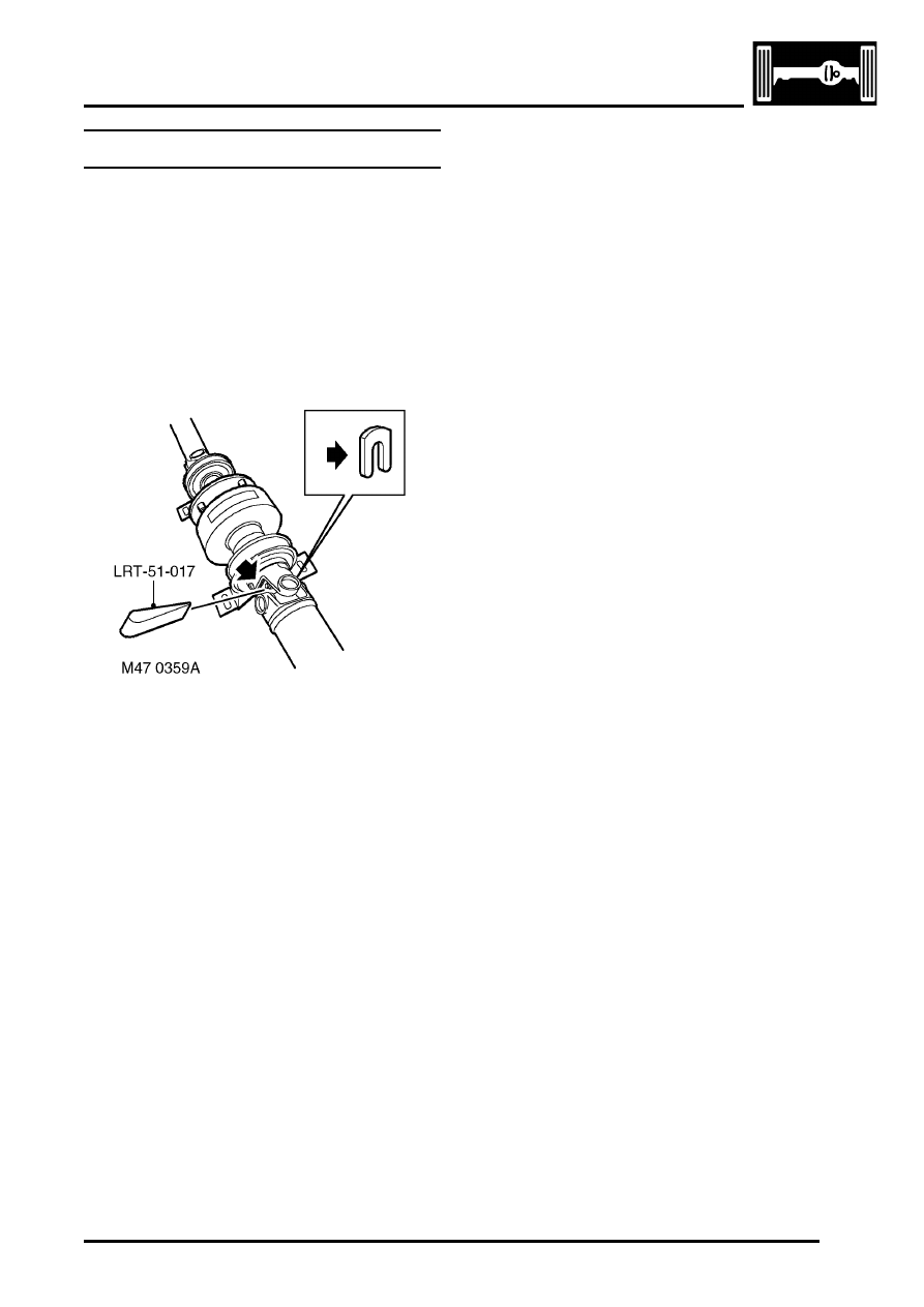
coupling and slide out 'U' washer.
4. To disengage the splines, insert wedge LRT-
51-017 between the bolt head and the universal
joint yoke. Screw the bolt in or out to correctly
position the wedge between the yoke and the
bolt head. Drive the wedge in squarely to
separate the components.
5. Adjust bolt engagement as necessary to
maintain contact between the wedge and the
bolt head.
6. Remove bolt and tab washer, pull propeller
shaft from viscous coupling. Discard tab
washer and bolt if damaged.
Refit
1. Clean mating faces and splines on propeller
shaft and viscous coupling.
2. Engage splines between propeller shaft and
viscous coupling shaft assembly and push
home propeller shaft as far as possible.
3. Partially fit bolt and new tab washer, position 'U'
washer between tab washer and spline yoke.
4. Tighten bolt to 65 Nm (48 lbf.ft)to fully seat
splines and secure with tab washer.
5. Fit propeller shaft assembly.