Freelander 1. Manual - part 89


  Index      Land Rover     Freelander 1 - service manual 2002 year


Search            


Content   ..  87  88  89  90   ..


Freelander 1. Manual - part 89


ENGINE - K SERIES KV6

REPAIRS 12-3-47

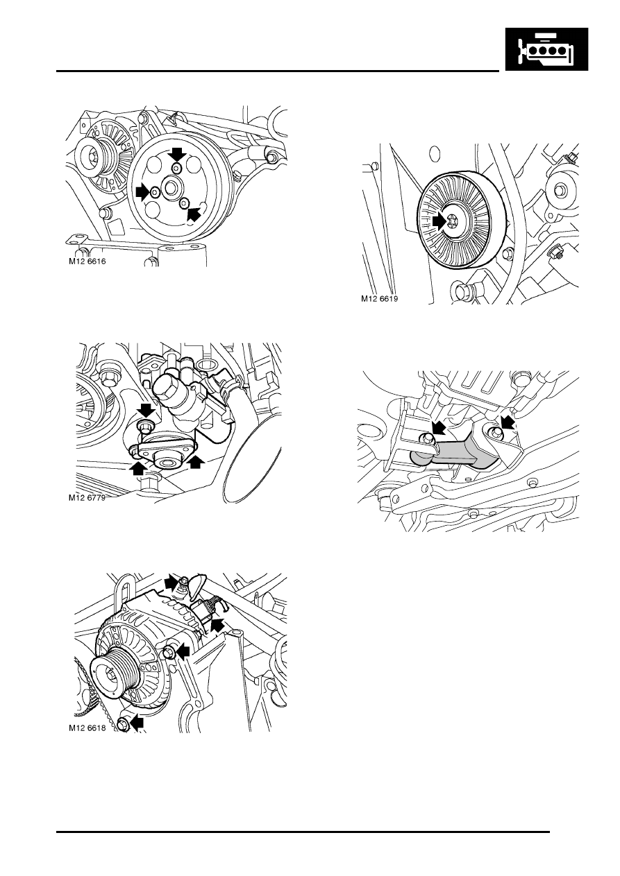
12. Remove 3 Torx screws securing PAS pump 

pulley and remove pulley.

13. Remove 3 bolts securing PAS pump to front 

mounting plate and tie pump aside.

14. Release alternator battery lead terminal cover, 

loosen terminal nut and disconnect lead from 
terminal.

15. Disconnect multiplug from alternator.

16. Remove lower bolt and upper nut and bolt 

securing alternator to front mounting plate.

17. Remove alternator.

18. Remove Torx screw securing idler pulley to 

front mounting plate and remove pulley.

19. Loosen bolt securing lower engine steady to 

front subframe.

20. Remove bolt securing lower engine steady to 

sump mounting,  release lower engine steady 
from sump mounting.

M12 6597

ENGINE - K SERIES KV6

12-3-48 REPAIRS

21. Remove 3 bolts securing camshaft timing belt 

RH front cover and remove cover.

22. Remove 3 bolts securing camshaft timing belt 

LH front cover and remove cover.

23. Assemble  LRT-12-161  to  LRT-12-199 and 

secure with clamp bolt.

24. Insert LRT-12-161 with LRT-12-199 into 

crankshaft pulley, loosen and remove pulley 
bolt.

CAUTION: Ensure crankshaft does not 
rotate during above operation.

25. Remove tools LRT-12-161 and LRT-12-199 

from crankshaft pulley, remove pulley.

26. Remove 3 bolts securing camshaft timing belt 

lower cover to cylinder block and remove cover.

ENGINE - K SERIES KV6

REPAIRS 12-3-49

27. Remove 2 bolts securing ancillary drive belt 

tensioner and remove tensioner.

28. Note fitted position of heat shield on A/C 

compressor and remove 3 bolts securing A/C 
compressor to front mounting plate and 
cylinder block. Release A/C compressor and 
heat shield and position aside.

29. Remove bolt securing dipstick tube to cylinder 

block.

30. Depress and hold down dipstick tube locking 

collar, remove dipstick tube from engine sump.

31. Remove rubber blanking plug from around 

camshaft timing belt tensioner.

M12 6626

M12 6672

ENGINE - K SERIES KV6

12-3-50 REPAIRS

32. Remove 3 bolts securing engine front mounting 

plate and lifting bracket to cylinder block.

33. Remove bolt securing lifting bracket to RH 

cylinder head and remove lifting bracket.

34. Remove 2 bolts securing IRD support bracket 

to engine front mounting plate.

35. Remove 5 bolts and 2 pillar bolts securing 

engine front mounting plate to cylinder block.

36. With care, release and remove front mounting 

plate from engine.

37. Insert a suitable 1.5 mm diameter pin through 

hole in tensioner body and into hole in plunger.

NOTE: If holes in body and plunger are not 
aligned, move tensioner backplate using a 
suitable broad bladed screwdriver; this will 
move plunger sufficiently to enable pin to be 
inserted.

38. Remove and discard 2 Patchlok bolts securing 

tensioner to cylinder block and remove 
tensioner.

CAUTION: Exercise great care when 
removing bolts, do not apply excessive 
torque. If bolts appear to be seized, apply 
suitable anti-seize lubricant prior to 
removing bolts. DO NOT loosen Allen screw 
securing tensioner pulley.

39. If camshaft timing belt is to be refitted, mark 

direction of rotation on timing belt before 
removal.


Content   ..  87  88  89  90   ..