Discovery 2. Manual - part 424


  Index      Land Rover     Land Rover Discovery 2 - service manual 1999 year


Search            


Content   ..  422  423  424  425   ..


Discovery 2. Manual - part 424


ENGINE - TD5

OVERHAUL 12-1-93

Timing chain and sprockets 

$% 12.65.13.01 

Disassembly

1. Remove cylinder head gasket.  


 + 

 ENGINE - Td5, OVERHAUL, Gasket 

- cylinder head.

CAUTION: If timing chain tensioner is to be 
replaced, ensure tensioner is correct for 
engine. Tensioner bodies are colour coded 
as follows: Engine Serial No. Prefixes 10P to 
14P – BLACK with, additionally on later 
engines, YELLOW on tensioner hex. head. 
Serial No. Prefixes 15P to 19P – body is 
colour coded YELLOW. Later tensioners 
may be fitted to early engines provided that 
the modified adjustable guide is also fitted.

2. Remove 3 bolts securing damper to crankshaft 

pulley,  remove damper. 

3. Fit  LRT-51-003  to crankshaft pulley.  
4. Secure tool using 2 bolts.
5. Using assistance, restrain engine and remove 

crankshaft pulley  bolt; discard bolt.

WARNING: CRANKSHAFT BOLT IS 
TIGHTENED TO 460 Nm (340 lbf.ft), ENSURE 
ENGINE IS ADEQUATELY RESTRAINED.

6. Remove crankshaft pulley.

7. Remove sump gasket.  


 ENGINE - Td5, OVERHAUL, Gasket 

- engine sump.

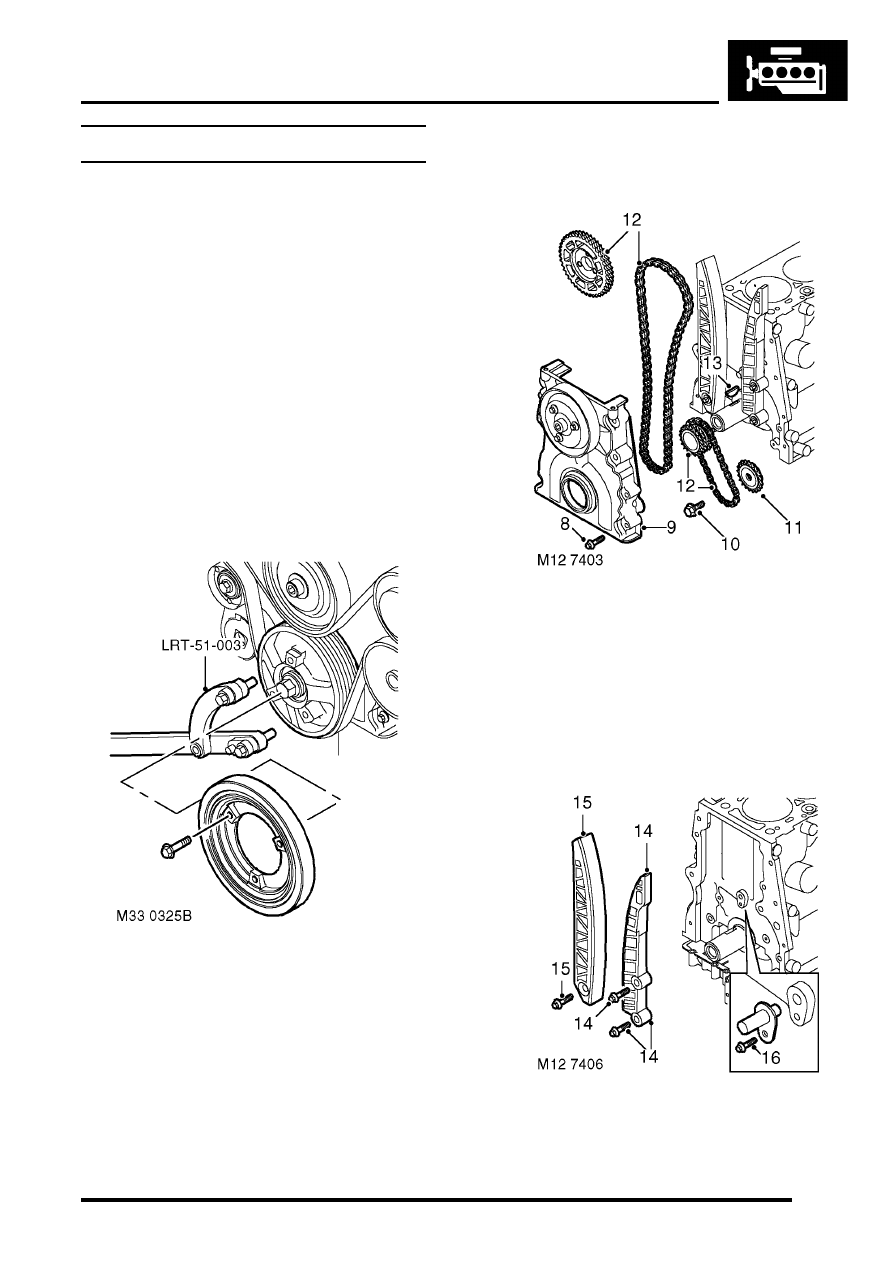
8. Noting their fitted position, remove 8 bolts 

securing timing  chain cover. 

9. Release timing chain cover from locating 

dowels, remove cover. 

10. Remove bolt securing oil pump drive sprocket. 
11. Remove oil pump drive sprocket.
12. Remove camshaft and crankshaft sprockets 

together with timing and  oil pump drive chains.

13. Remove Woodruff key from crankshaft. 

14. Remove 2 bolts and remove timing chain fixed 

guide. 

ENGINE - TD5

12-1-94 OVERHAUL

15. Remove bolt and remove timing chain 

adjustable guide. 

16. Remove bolt and remove timing chain 

lubrication jet. 

17. Using tool  LRT-12-092, remove and discard oil 

seal from timing cover. 

Inspection

1. Clean all components.
2. Check condition of timing chain running 

surfaces on adjustable and  fixed guides.

CAUTION: Adjustable guide fitted to Engine 
Serial No. Prefixes 15P to 19P may be fitted 
to early engines provided that timing chain 
tensioner having a YELLOW coloured body 
is also fitted.

3. Check timing chains and sprockets for signs of 

wear.

CAUTION: Timing chains and sprockets 
fitted to Engine Serial No. Prefixes 15P to 
19P may be fitted to early engines as an 
assembly only, oil pump drive sprockets are 
interchangeable. Later timing chains have 
BRONZE coloured timing links.

4. Check that drilling in timing chain lubrication jet 

is clear.

5. Clean oil seal recess in timing cover and oil seal 

running  surface on crankshaft.

6. Remove all traces of sealant from mating faces 

of timing cover  and cylinder block using 
suitable solvent. 

CAUTION: Do not use metal scrapers.

7. Ensure bolt and dowel holes are clean and dry.
8. Clean oil pump sprocket bolt threads.

Reassembly

1. Fit timing chain lubrication jet. 
2. Fit  timing chain lubrication jet Torx screw  and 

tighten to 10 Nm (7 lbf.ft).

3. If crankshaft has been rotated, check that No.1 

piston is at TDC  using the following 
procedures:

4. Temporarily fit and lightly tighten a new 

crankshaft pulley bolt.

5. Assemble a magnetic base DTI to cylinder 

block top face, position  stylus to cylinder block 
face and zero gauge.

6. Using crankshaft pulley bolt, rotate crankshaft 

clockwise until  No.1 piston is at top of its stroke 
and woodruff key slot in crankshaft  is at 12 
o'clock position.

7. Position stylus of DTI to No.1 piston crown and 

rotate crankshaft  until highest reading is 
indicated on DTI.

8. Check that Woodruff key slot is still at 12 

o'clock position  indicating No.1 piston is at 
TDC firing.

9. Remove DTI.

10. Remove and retain crankshaft pulley bolt.
11. Fit Woodruff key to crankshaft.
12. Fit oil pump drive chain to rear row of teeth on 

crankshaft  sprocket - i.e. teeth furthest away 
from timing mark on sprocket.

13. Fit sprocket to crankshaft ensuring that timing 

mark on sprocket  is facing towards front end of 
crankshaft.

14. Fit oil pump drive sprocket to oil pump and drive 

chain ensuring  that 'D' shape on sprocket is 
located on flat on oil pump drive shaft.

ENGINE - TD5

OVERHAUL 12-1-95

15. Apply Loctite 242 to threads of oil pump drive 

sprocket bolt,  fit bolt and tighten to 25 Nm (18 
lbf.ft).

16. Fit timing chain fixed guide, fit bolts and tighten 

to:

l

 M6 bolt – 10 Nm (7 lbf.ft)

l

M10 bolt – 45 Nm (34 lbf.ft)

17. Fit timing chain adjustable guide, fit bolt and  

tighten  to 25 Nm (18 lbf.ft).

18. Fit camshaft sprocket to timing chain with 

timing mark on sprocket  between the 2 
coloured links, suitably retain sprocket on 
chain.

19. Fit timing chain to crankshaft sprocket aligning 

coloured link to  timing mark on sprocket. 

20. Ensure timing marks are positioned as shown - 

No.1 piston at  TDC firing.

21. Apply an even film of sealant  Part No. STC 

4600   to mating face of timing cover and 
spread to an even film using a roller.

CAUTION: Assembly and bolt tightening 
must be completed within 20 minutes of 
applying sealant.

22. Fit timing cover, fit bolts in their original fitted 

positions and   working from the centre 
outwards, tighten progressively to  27 Nm (20 
lbf.ft).

23. Fit oil seal guide, from seal kit over end of 

crankshaft.

24. Fit new oil seal into timing cover using tool   

LRT-12-156.   

CAUTION: Oil seal must be fitted dry.

25. Remove tool  LRT-12-156  and oil seal guide.
26. Fit crankshaft pulley, fit and lightly tighten  

crankshaft pulley bolt.  

ENGINE - TD5

12-1-96 OVERHAUL

27. Fit tool  LRT-51-003 to crankshaft pulley, 

secure with 2 bolts. Using assistance, restrain 
engine and using a torque multiplier   tighten 
bolt to 450 Nm (340 lbf.ft).

WARNING: DUE TO THE HIGH TORQUE 
LOADING REQUIRED, IT IS ESSENTIAL 
THAT ENGINE IS ADEQUATELY 
RESTRAINED.

28. Remove tool  LRT-51-003.
29. Position damper to crankshaft pulley, fit 3 bolts  

and tighten to 80 Nm (60 lbf.ft).

30. Fit sump gasket


 + 

 ENGINE - Td5, OVERHAUL, Gasket 

- engine sump.

31. Fit cylinder head gasket.  


 + 

 ENGINE - Td5, OVERHAUL, Gasket 

- cylinder head.

Bearings - connecting rods  

$% 12.17.16.01 

Disassembly

1. Remove oil pump.  


 ENGINE - Td5, OVERHAUL, Pump - 

oil.

2. Mark cylinder reference number on each 

connecting rod big-end  bearing cap. 

3. Make suitable alignment marks between each 

big-end bearing cap  and connecting rod.

CAUTION: Due to the 'fracture split' method 
of manufacturing  connecting rods, 
incorrect fitment of cap to rod will damage 
mating  faces and necessitate replacement 
of connecting rod assembly.

4. Rotate crankshaft clockwise until No.1 big-end 

is at BDC.

5. Remove and discard 2 bolts securing each 

connecting rod big-end  bearing cap. 

6. Remove bearing cap, remove and discard big-

end bearing shell.

7. Push connecting rod up cylinder bore until 

connecting rod  is clear of crankshaft journals.

CAUTION: Ensure that connecting rod does 
not contact cylinder bore or oil squirt jet and 
piston does not contact the valves or EUI's 
if the cylinder head is fitted.


Content   ..  422  423  424  425   ..