Discovery 2. Manual - part 292
AIR CONDITIONING
DESCRIPTION AND OPERATION
82-7
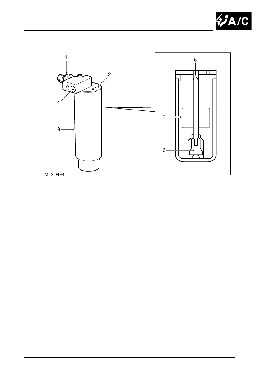
Receiver drier
1 Dual pressure switch
2 Inlet connection
3 Housing
4 Outlet connection
5 Outlet tube
6 Screen
7 Desiccant
The receiver drier removes moisture and solid impurities from the refrigerant and also acts as a refrigerant reservoir.
The receiver drier is clamped to a bracket in front of the condenser. The receiver drier housing is manufactured in
aluminium and contains a desiccant to absorb moisture. A mesh screen in the housing removes solid impurities. Inlet,
outlet and dual pressure switch connections are located in the top of the housing.
Liquid refrigerant enters the receiver drier, passes through the desiccant and mesh screen, and through a tube to the
outlet connection.