Discovery 2. Manual - part 293
AIR CONDITIONING
DESCRIPTION AND OPERATION
82-11
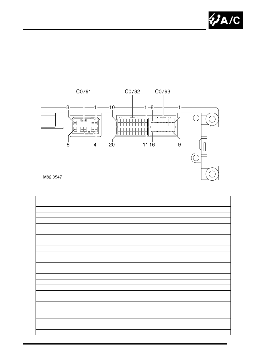
ATC ECU
The ATC ECU is installed in the centre of the fascia, below the radio. An integral control panel on the ATC ECU
contains switches for system control inputs and a LCD to provide system status information.
Inputs from sensors and the control panel switches are processed by the ATC ECU, which then outputs the
appropriate control signals.
ATC ECU connectors
ATC ECU connector pin details
Connector/Pin
No.
Description
Input/Output
C0791
1
Battery power supply
Input
2
Ignition power supply
Input
3
Sensor power supply
Output
4
Earth
-
5
Display illumination
Input
6
Not used
-
7
Not used
-
8
Sensor earth
-
C0792
1
Night lighting/dimming
Input
2
Vehicle speed
Input
3
Hand of drive
Input
4
Distribution flaps position
Input
5
Heater coolant temperature
Input
6
External air temperature
Input
7
In-car air temperature
Input
8
Blower power transistor collector voltage
Input
9
Not used
-
10
Not used
-
11
Windscreen heater status
Input
12
Rear screen heater status
Input
13
Rear air conditioning ON
Input