Land Rover Discovery. Manual - part 206
ELECTRICAL
3
REPAIR
BATTERY
Service repair no - 86.15.01
NOTE: Some vehicles are fitted with a
battery backed-up sounder. Disconnecting
the vehicle battery will cause the alarm to
sound unless the following procedure is followed:
1. Turn starter switch ’ON’ then ’OFF’.
2. Disconnect battery WITHIN 15 SECONDS (see
WARNING).
If alarm is accidentally activated, ensure sounder is
connected and silence by turning the starter switch to
position II.
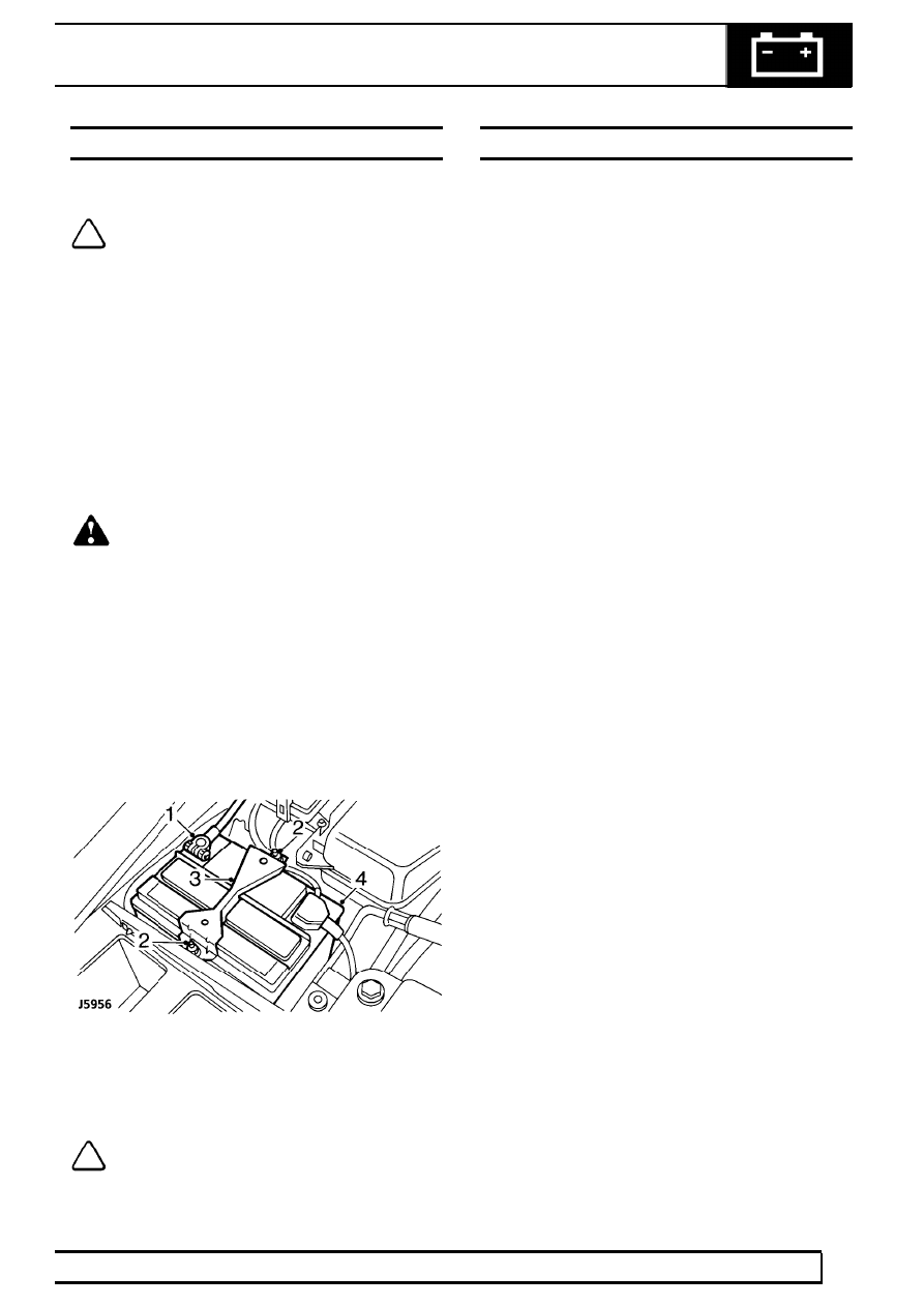
Remove
WARNING: During battery removal or
before carrying out any repairs or
maintenance to electrical components
always disconnect battery negative lead first. If
positive lead is disconnected with negative lead in
place, accidental contact of wrench to any
grounded metal part could cause a severe spark,
possibly resulting in personal injury. Upon
installation of battery connect positive lead first.
3. Disconnect both battery leads, negative first.
4. Release four nuts securing battery bracket in
position.
5. Remove bracket.
6. Remove battery.
Refit
7. Reverse removal procedure.
NOTE: Coat battery clamps and terminals
with petroleum jelly before refitting.
DISTRIBUTOR-LUCAS 35 DLM8 - V8i
Service parts
1. Cap
2. HT brush and spring
3. Rotor arm
4. Insulation cover
5. Pick-up module and base plate assembly
6. Vacuum unit
7. Amplifier module
8. ’O’-ring oil seal
9. Gasket