Land Rover Discovery. Manual - part 205
ELECTRICAL
5
FAULT DIAGNOSIS
TEST 6:
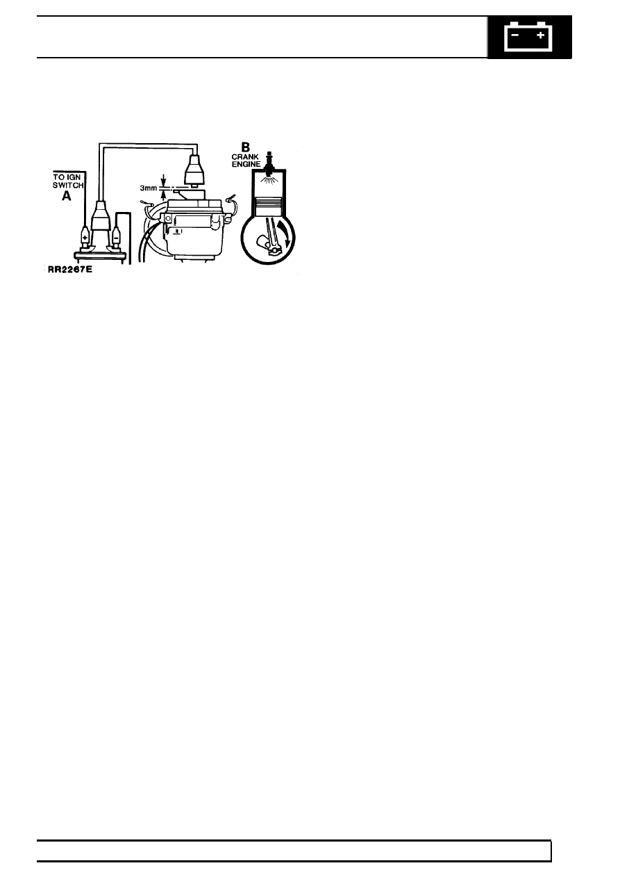
Rotor Arm
Remove distributor cover. Disconnect coil H.T. lead
from cover, using insulated pliers hold about 3mm
above rotor arm electrode and crank the engine.
There should be no H.T. sparking between rotor and
H.T. lead. If satisfactory carry out Test 7.
If H.T. sparking occurs, an earth fault on rotor arm is
indicated. Fit new rotor arm. If engine will not start
carry out Test 7.
TEST 7:
Visual and H.T. Cable Checks
Examine:
Should be:
1.
Distributor Cover
Clean, dry, no tracking marks
.....................................................
2.
Coil Top
Clean, dry, no tracking marks.
...................................................................
3.
H.T. Cable Insulation
Must not be cracked, chafed or perished
...............................................
4.
H.T. Cable Continuity
Must not be open circuit
..............................................
5.
Sparking Plugs
Clean, dry, and set to correct gap
........................................................
NOTE:
1.
Reluctor
Must not foul pick-up or leads
...................................................................
2.
Rotor and Insulation Cover
Must not be cracked or show signs of tracking marks
.....................................