Land Rover Discovery. Manual - part 73
19
FUEL SYSTEM
8
REPAIR
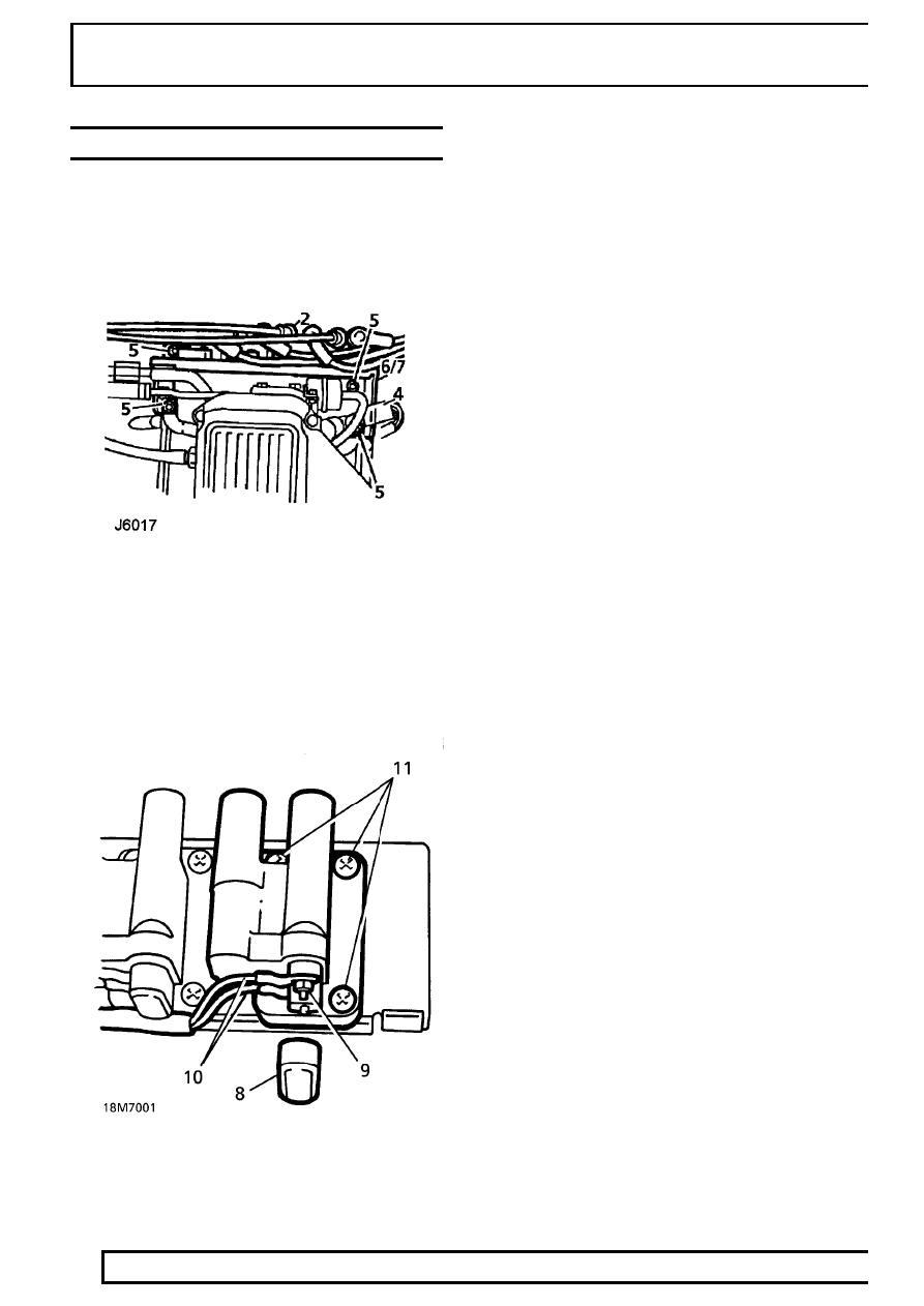
IGNITION COILS
Service repair no - 18.20.45 - Set
Service repair no - 18.20.43 - Each
Service repair no - 18.20.44 - Extra - Each
Remove
1. Disconnect battery negative lead.
2. Disconnect H.T. leads from ignition coils. Note
positions of leads.
3. Place H.T. leads aside.
4. Disconnect ignition coil multiplug.
5. Remove 4 nuts securing coil bracket.
6. Release ignition coil bracket from inlet manifold
studs.
7. Manoeuvre coil/bracket assembly from behind
plenum chamber and remove.
8. Remove terminal cover. Note lead positions.
9. Remove 2 nuts securing leads to coil terminals.
10. Remove leads from terminals.
11. Remove 3 Torx screws securing ignition coil to
bracket and remove coil.
Refit
12. Fit ignition coil to bracket. Secure with screws.
13. Connect leads to terminals. Secure with nuts.
14. Fit terminal cover.
15. Position ignition coil bracket on inlet manifold
studs.
16. Secure fuel rail and ignition coil bracket with
nuts. Tighten to
8 Nm.
17. Connect multiplug.
18. Connect H.T. leads to respective coil towers.
19. Reconnect battery negative lead.