Land Rover Discovery. Manual - part 38


  Index      Land Rover     Land Rover Discovery - service 1995-1996 year


Search            


Content   ..  36  37  38  39   ..


Land Rover Discovery. Manual - part 38


Mpi

1

DESCRIPTION AND OPERATION

DESCRIPTION

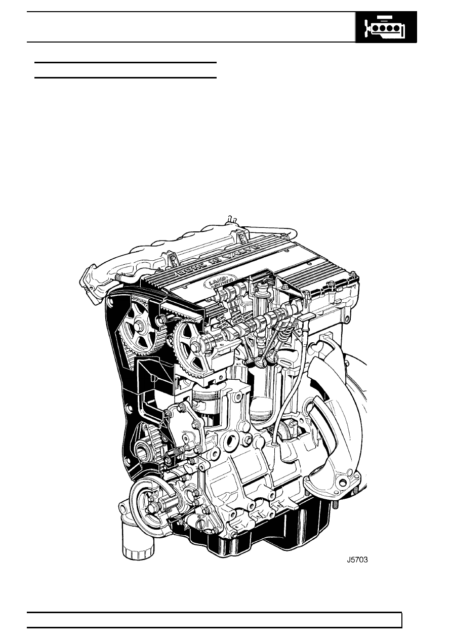
The ’T’ Series engine is a four cylinder, water cooled
unit comprising a cast iron cylinder block, aluminium
alloy cylinder head and twin aluminium alloy camshaft
carriers.

The cylinder block incorporates direct bored,
siamesed cylinder bores which provide good structural
rigidity. The crankshaft is carried in five main
bearings, end-float being controlled by thrust washers
positioned each side of the centre main bearing.

The main bearing caps are located to the cylinder
block by dowels; the bearing shells fitted to Nos. 1, 3
and 5 bearings are fully grooved whilst those fitted to
Nos. 2 and 4 bearings are plain.

The cylinder head carries twin camshafts operating
four valves per cylinder via hydraulic tappets. Both
camshafts are driven by the timing belt and run
directly in journals line bored in the cylinder head and
camshaft carriers. The plastic camshaft covers are
bolted to the camshaft carriers.

12

ENGINE

2

DESCRIPTION AND OPERATION

The aluminium alloy, tin coated pistons have two
compression and an oil control ring and are secured
to the connecting rods by semi-floating gudgeon pins
which are an interference fit in the small-end bush.
Gudgeon pins are offset towards the thrust side of the
pistons to reduce frictional drag.

Plain, big-end bearing shells are fitted to each
connecting rod.

The internally toothed timing belt is driven from a gear
which is keyed to the crankshaft, belt tension being
controlled by a semi-automatic tensioner.

The trochoidal type oil pump is mounted on the front
of the engine and carries the crankshaft front oil seal.
Drive to the pump is via a Woodruff key inserted in the
crankshaft.

Mpi

3

DESCRIPTION AND OPERATION

Lubrication

Oil is drawn from the pressed steel sump through a
strainer (1) and into the oil pump (2); excess pressure
being relieved by a pressure relief valve (3) integral
with the pump. The low oil pressure sensor (4)
registers the oil pressure in the main oil gallery on the
outflow side of the filter. Pressurised oil passes
through the full flow oil filter (5) to internal drillings in
the crankshaft where it is directed to each main
bearing and to the big end bearings via Nos. 1, 3 and
5 main bearings (6). An internal drilling in the cylinder
block directs oil, via a restrictor (7) to the cylinder
head where it passes through further internal drillings
to the hydraulic tappets and camshaft journals (8).
Gudgeon pin and small-end bush lubrication is by
splash from the big-end bearings.

Crankcase ventilation

With the exception of two hoses connected from the
inlet camshaft cover to the inlet manifold and throttle
housing all crankcase ventilation is via internal voids
in the cylinder head and block. The inlet camshaft
cover carries a wire gauze flame trap located over the
breather pipe connections.

12

ENGINE

4

DESCRIPTION AND OPERATION

CYLINDER BLOCK COMPONENTS

1. Cylinder block
2. Knock sensor
3. Crankshaft sensor
4. Bolt - crankshaft sensor
5. Locating dowel - cylinder head
6. Bolt - connecting rod
7. Piston
8. Piston ring - top compression
9. Piston ring - 2nd compression

10. Piston ring - oil control
11. Gearbox adapter plate
12. Bearing shell - big end - upper
13. Flywheel
14. Bolt - flywheel
15. Torx screw - gearbox adapter plate
16. Blanking plate
17. Bolt - blanking plate
18. Gasket
19. Bolt - crankshaft rear oil seal housing
20. Crankshaft rear oil seal and housing
21. Bolt - coolant pump cover
22. Coolant pump cover
23. Impeller
24. Sealing rings
25. ’O’ ring
26. Bolts - coolant pump
27. ’O’ ring
28. Coolant pump body
29. Thrust washer halves - upper
30. Bearing shell - main bearing - upper
31. Locating dowel - oil pump
32. Locating dowel - flywheel
33. Gudgeon pin

34. Crankshaft
35. Bearing shell - big end - lower
36. Bearing cap - big end
37. Nut - big end bearing cap
38. Locating dowel - main bearing cap
39. Bearing caps - main bearings
40. Bolt - main bearing cap
41. Thrust washer halves - lower
42. Bearing shell - main bearing - lower
43. Woodruff keys
44. Dipstick
45. Bolt - dipstick tube
46. Dipstick tube
47. Bolts - sump
48. Gasket - sump
49. ’O’ ring
50. Oil strainer
51. Bolts - oil strainer
52. Sump
53. Washer - drain plug
54. Drain plug
55. Oil filter element
56. Crankshaft front oil seal
57. Bolts - oil pump
58. Gasket - oil pump
59. Oil pump
60. Oil pressure switch
61. Crankshaft spigot bush
62. Crankshaft spigot bearing
63. Locating dowel - coolant pump
64. Connecting rod
65. Bolts belt tensioner mounting plate
66. Belt tensioner mounting plate
67. Bolt - gearbox adapter plate


Content   ..  36  37  38  39   ..