Defender 300Tdi (1996+). Manual - part 89


  Index      Land Rover     Defender 300Tdi - service repair manual 1996 year


Search            


Content   ..  87  88  89  90   ..


Defender 300Tdi (1996+). Manual - part 89


HEATING AND VENTILATION

1

DESCRIPTION AND OPERATION

HEATING AND VENTILATION SYSTEM

Description

The heating and ventilation system is standard on all
models. Air conditioning is an optional system which
provides fully integrated climate control for the vehicle
interior.

The heater assembly, comprising a matrix housed in a
distribution unit and a variable speed blower motor, is
located on one side of the engine compartment and
attached directly to the fascia bulkhead.

The heating controls are positioned on the outside of
the instrument binnacle and cable linked to
mechanical flaps in the distribution unit.
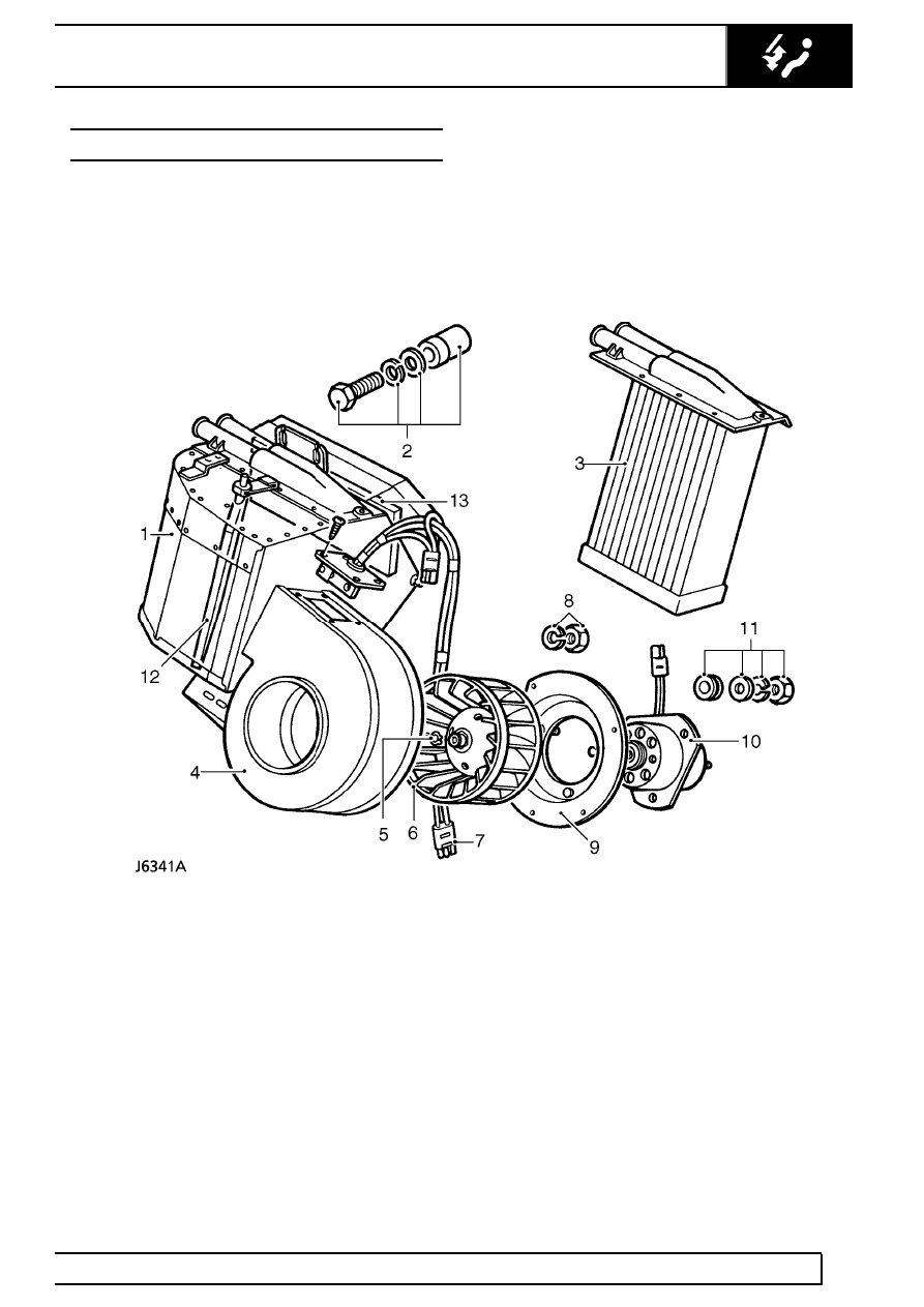
Heater assembly

1. Heater distribution unit
2. Fixings, heater to fascia bulkhead
3. Heater matrix
4. Blower motor housing
5. Circlip, impeller to blower motor
6. Impeller
7. Resistor unit and harness connector

8. Fixings, blower motor mounting plate
9. Mounting plate, blower motor

10. Blower motor
11. Fixings, blower motor to mounting bracket
12. Temperature flap, air flow to heater matrix
13. Air flap, air supply to plenum chamber (heater

duct)

80

HEATING AND VENTILATION

2

DESCRIPTION AND OPERATION

HEATER OPERATION

The heater matrix (3), located in the distribution unit
(1), see J6341, is connected to the engine cooling
system. As water is circulated continuously through
the matrix, a selection of heated or ambient air is
controlled by two flaps within the distribution unit. The
temperature flap (12) controls the amount of ambient
air to the heater matrix, air being supplied

through a ducted vent on top of the vehicle front wing
to the blower motor (volute) housing (4). The blower
motor (10) can be used to boost the air flow into the
distribution unit. The air flap (13) controls the supply of
heated or ambient air from the heater unit into a
plenum chamber integeral with the vehicle fascia. Two
flaps in the plenum chamber (heater duct) distribute
the air flow to either the footwell vents or windscreen
demister vents as shown.

HEATER CONTROLS

1. Temperature control

Move the lever downwards to increase air
temperature or up to decrease air temperature.

2. Air distribution control

Lever fully up - windscreen vents only.
Lever midway - footwell and windscreen vents.
Lever fully down - footwell vents.

3. Blower motor fan speed control

Move the lever progressively downwards to increase
fan speed. With the control at ’0’ the fan is switched
off and the volume of air entering the passenger
compartment is solely dependent on ram air when the
vehicle is moving.

HEATING AND VENTILATION

3

DESCRIPTION AND OPERATION

Fresh air vents

Two fresh air vents are fitted in the windscreen frame
and are controlled independently of the vehicle
heating system. Each vent is operated separately.

To open the vents, push the lever to the right and then
down to the required position.

HEATING AND VENTILATION

1

REPAIR

HEATER UNIT

Service repair no - 80.20.01

Remove

1. Remove bonnet and disconnect battery.
2. Remove radiator bottom hose at radiator union

and drain cooling system

See COOLING

SYSTEM, Repair, Drain and refill cooling
system 
.

3. Slacken clips and remove heater hoses at

heater box unions.

4. Remove outer cable securing clips.
5. Slacken trunnions and remove control cables

from heater vent flap levers.

6. Remove heater wiring harness securing loop.
7. Disconnect harness multi-plug.
8. Remove interior bulkhead trim.
9. Remove lower nuts and bolts securing the

heater unit to the bulkhead.

10. Slacken heater unit upper retaining bolts.
11. Manoeuvre heater unit, complete with blower

motor, clear of air inlet duct and remove from
engine compartment.

12. If existing heater unit is to be refitted, remove

sealing rubber.
For heater matrix removal

See Heater matrix .

For blower motor removal

See Blower motor .

Refit

13. Smear a new heater unit sealing rubber with a

suitable impact adhesive and fit to heater.

14. Manoevre heater unit into position in engine

compartment, fit blower motor to air inlet duct
and locate upper fixing bolts.

15. Loosely fit heater unit lower fixing bolts.
16. Fully tighten upper fixing bolts.
17. Fully tighten lower fixings and refit interior

bulkhead trim.

18. Secure wiring harness and reconnect multi-plug.
19. Fit control cables to vent flap trunnions and

secure with outer cable clips.

20. Connect heater hoses.
21. Fit radiator bottom hose and refill cooling system

See COOLING SYSTEM, Repair, Drain and
refill cooling system 
.

22. Fit bonnet and reconnect battery.


Content   ..  87  88  89  90   ..