Defender 300Tdi (1996+). Manual - part 87
76
CHASSIS AND BODY
32
REPAIR
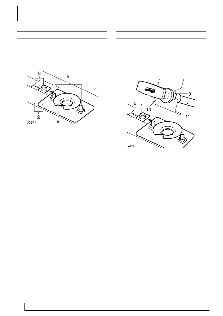
BONNET LOCK
Service repair no - 76.16.21
Remove
1. Open bonnet.
2. Mark position of guide plate and lock to bonnet
platform.
3. Remove 8 screws securing grille.
4. Remove grille.
5. Remove 2 bolts securing guide plate and lock.
6. Remove guide plate.
7. Release spring securing lock to bonnet platform.
8. Slacken clamping bolt securing bonnet release
cable.
9. Remove lock.
Refit
10. Fit spring between lock and bonnet platform.
11. Position lock and guide plate to bonnet platform
and nip up bolts.
12. Position guide plate and lock to position marks
and tighten bolts to
10 Nm (7 lbf/ft).
13. Fit cable to lock and tighten clamping bolt.
14. Check operation of release cable and adjust if
necessary.
15. Fit grille and tighten securing screws.
16. Close bonnet.
BONNET RELEASE CABLE
Service repair no - 76.16.29
Remove
1. Open bonnet.
2. Remove 8 screws securing grille.
3. Remove grille.
4. Slacken clamping bolt securing bonnet release
cable.
5. Remove cable from lock.
6. Release cable from clip on underside of bonnet
platform.
7. Feed cable through valance and collect
grommet.
8. Release cable from clip fixed to wheelarch under
expansion tank.
9. Loosen clamping nut securing bonnet release
handle to mounting bracket.
10. Remove bonnet release handle from mounting
bracket.
11. Withdraw cable through bulkhead.
Refit
12. Feed cable through bulkhead and fit bonnet
release handle to mounting bracket. Tighten
clamping nut.
13. Route cable behind expansion tank and fit to
securing clip.
14. Feed cable through valance.
15. Fit grommet between cable and valance.
16. Fit cable to securing clip on underside of bonnet
platform.