Defender 300Tdi (1996+). Manual - part 86


  Index      Land Rover     Defender 300Tdi - service repair manual 1996 year


Search            


Content   ..  84  85  86  87   ..


Defender 300Tdi (1996+). Manual - part 86


76

CHASSIS AND BODY

28

REPAIR

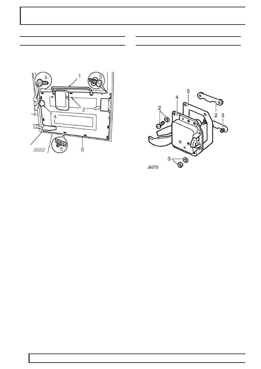
TAIL DOOR TRIM CASING

Service repair no - 76.34.09

Remove

1. Unscrew 2 bolts and remove grab handle from

rear door.

2. Remove 2 screws and detach wiper motor cover.
3. Remove 7 screws securing trim casing to door.
4. Remove 2 screws and lift wiper motor harness

cover from harness support bracket.

5. Carefully release 8 clips securing trim casing to

door.

6. Remove trim casing and collect door lock cover.

Refit

7. Position door lock cover, fit trim casing and

secure with clips.

8. Fit harness cover and secure with two screws.
9. Secure door panel with retaining screws.

10. Position wiper motor cover and secure with 2

screws.

11. Position grab handle and secure with 2 bolts.

TAIL DOOR LOCK

Service repair no - 76.37.16

Remove

1. Remove door casing

See Tail door trim

casing .

2. Remove screws, washers and nut retainer plate

securing top of lock to door.

3. Remove nuts, washers and stud retainer plate

securing bottom of lock to door.

4. Withdraw lock assembly.
5. Remove door lock gasket.
6. Clean sealant from retainer plates.
7. Insert key into barrel.
8. Depress lock barrel plunger and withdraw barrel

from lock.

Refit

9. Fit new barrel into lock.

10. Apply sealant to lock retainer plates.
11. Fit lock to door with a new gasket.
12. Secure with retainer plates, screws, washers

and nuts.

13. Close door and check for correct latching with

striker. Adjust striker as necessary

See Tail

door striker - adjust .

14. Fit door casing

See Tail door trim casing .

CHASSIS AND BODY

29

REPAIR

TAIL DOOR STRIKER - ADJUST

Service repair no - 76.37.25

Adjust

1. Loosen striker securing screws.
2. Adjust striker and retighten screws.
3. Close door and check for correct latching with

door lock.

4. Carry out further adjustment as necessary. If full

adjustment cannot be achieved carry out
following:

5. Remove striker and nut plate.
6. Elongate holes in body metal which is

sandwiched between striker and nut plate.

7. Refit striker and adjust as necessary.

76

CHASSIS AND BODY

30

REPAIR

SUN ROOF

Service repair no - 76.83.01

Remove

1. Open sun roof fully.
2. Disengage spring lock from operating handle

catch.

3. Holding sun roof at both sides, release hinges

from locating brackets at front of outer frame.

4. Remove sun roof.
5. Starting from centre rear, peel headlining finisher

from inner frame.

6. Remove 18 screws securing inner frame to outer

frame and detach inner frame.

7. Lift outer frame from roof.

NOTE: Assistance may be required to
remove the sun roof assembly.

Refit

8. Clean roof area around outer frame seating.
9. Position outer frame on roof.

10. Fit inner frame to headlining and secure to outer

frame with 18 screws but do not fully tighten.

11. Check alignment of inner and outer frames with

roof mounting and headlining, adjust as
necessary, and fully tighten fixing screws to

10

Nm (7 lbf/ft).

12. Starting from centre rear, fit headlining finisher

lip into locating channel of inner frame.

13. Press finisher firmly over inner frame and

continue around complete frame, ensuring
finisher lies flat on headlining.

14. Fit sun roof hinges fully into locating brackets on

outer frame, and lower the glass panel.

15. Engage operating handle catch with spring lock

of outer frame and close sunroof.

CHASSIS AND BODY

31

REPAIR

INTERIOR MIRROR

Service repair no - 76.10.51

Remove

1. Prise interior mirror arm from mounting plate.
2. Remove 3 screws and remove mounting plate

from headlining.

Refit

3. Fit mounting plate to headlining.
4. Locate lower lug of mirror arm in mounting plate

aperture.

5. Press mirror arm firmly to engage spring clip in

mounting plate aperture.

SUN VISORS

Service repair no - 76.10.47

Remove

1. Raise sun visor.
2. Remove 2 screws and collect sun visor.

Refit

3. Position sun visor and secure with 2 screws.


Content   ..  84  85  86  87   ..