Defender 300Tdi (1996+). Manual - part 80
76
CHASSIS AND BODY
4
REPAIR
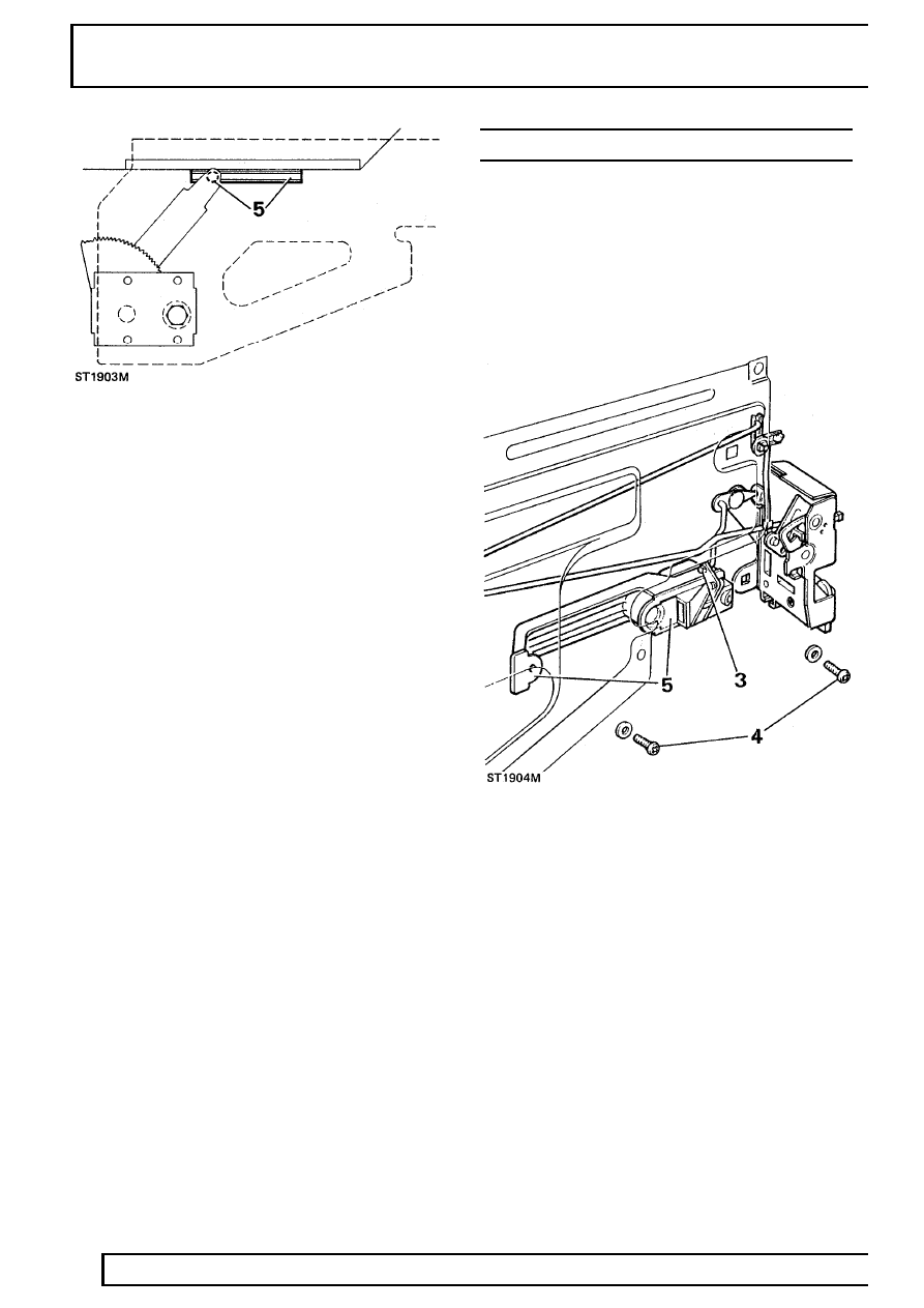
Refit
5. Insert lifting arm button into lifting channel.
6. Position regulator so that fixing holes line-up with
holes in mounting panel.
7. Secure with 4 screws and tighten evenly.
8. Temporarily fit handle and check that glass can
be raised and lowered smoothly without tight
spots.
9. Fit plastic sheet.
10. Fit door trim
See Door trim casing .
EXTERIOR HANDLE - REAR SIDE DOOR
Service repair no - 76.58.02
Remove
1. Remove door trim casing
See Door trim casing
.
2. Peel back sufficient of plastic sheet to gain
access to handle mechanism.
3. Disconnect actuating rod from handle operating
lever.
4. Remove 2 screws and withdraw handle and
bezels.
Refit
5. Fit handle to door ensuring that both bezels are
in position - flat faces towards door and secure
with 2 screws.
6. Connect actuating rod to handle operating lever
and secure with spring clip.
7. Re-seal plastic sheet.
8. Fit door trim casing
See Door trim casing .