Defender 300Tdi (1996+). Manual - part 76
WHEELS AND TYRES
3
REPAIR
WHEEL BALANCING
CAUTION: It is essential that all wheel
balancing is carried out off the vehicle.
The use of on the vehicle balancing could
cause component damage or personal injury and
MUST NOT be attempted.
NOTE: Before attempting to balance a
wheel and tyre assembly clean all mud and
dirt deposits from both inside and outside
rims and remove existing balance weights.
Remove stones from the tyre tread in order to avoid
operator injury during dynamic balancing and to obtain
the correct balance.
Inspect tyres for damage and correct tyre pressures
and balance according to the equipment
manufacturer’s instructions.
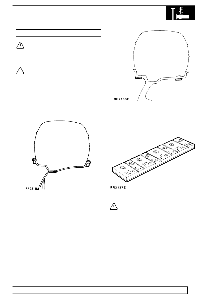
Steel wheels
Clean area of wheel rim and attach balance weights in
position shown.
Alloy wheels
Clean area of wheel rim and attach adhesive balance
weights in position shown. Cut through rear face of
weight strip to detach required weights.
CAUTION: Use only correct adhesive
balance weights to avoid damage to
aluminium wheel rim. DO NOT attempt to
use a steel wheel weight on an aluminium wheel.