Defender 300Tdi (1996+). Manual - part 66
FRONT SUSPENSION
5
REPAIR
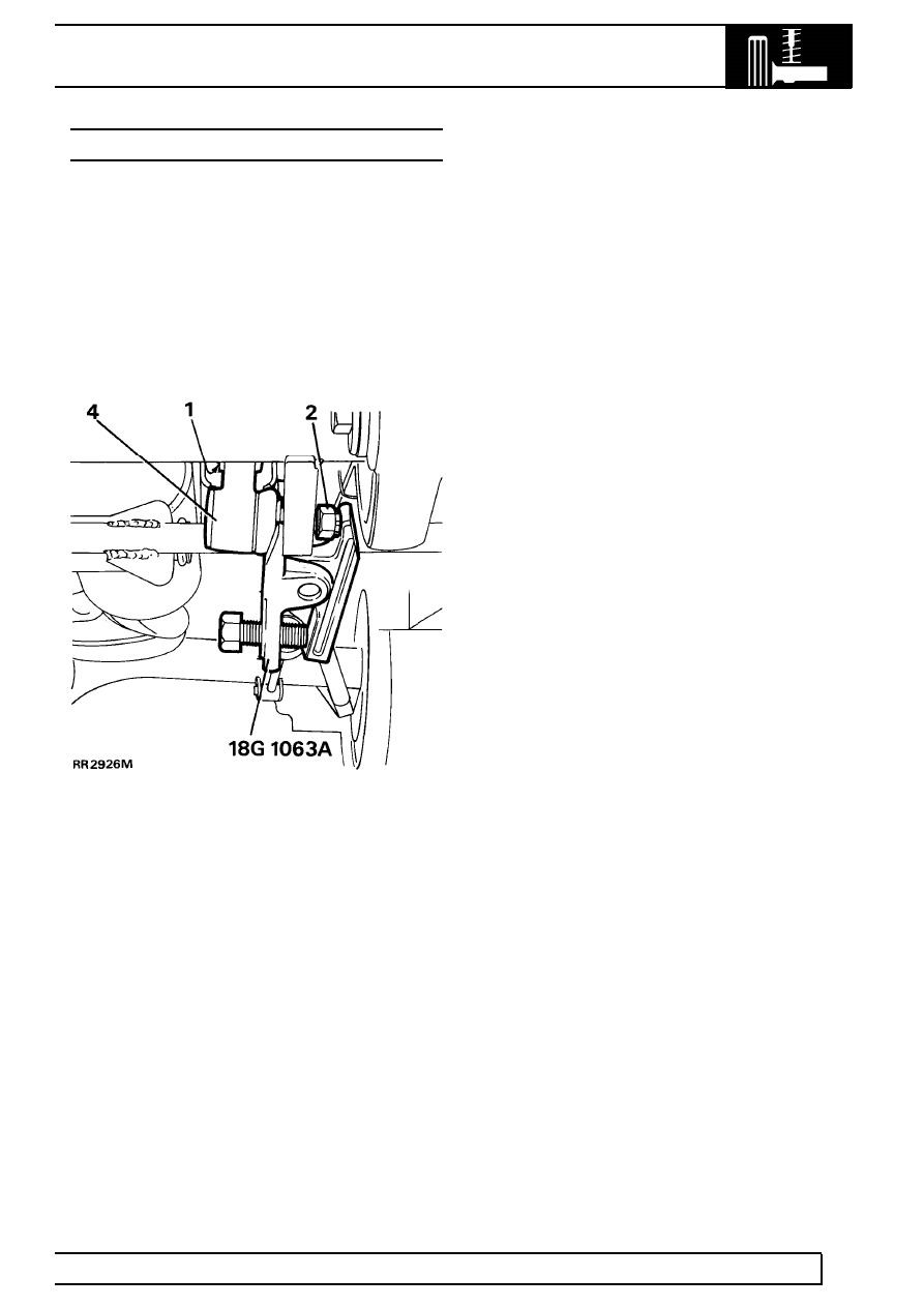
ANTI-ROLL BAR LINKS
Service repair no - 60.10.04.
Remove
1. Remove 2 nuts, bolts, washers and rubber
bushes from ball joint links.
2. Remove cotter pin and loosen castellated nut a
few turns.
3. Release link joint using special tool 18G 1063A
as shown.
4. Remove castellated nut and link.
Refit
5. Fit link and castellated nut. Ensure ball joint link
arm points up. Tighten nut to
40 Nm (30 lbf/ft)
and fit new cotter pin.
6. Align anti-roll bar to links.
7. Fit bolts, washers and rubber bushes using new
self locking nuts and secure anti-roll bar to links.
Tighten fixings to
68 Nm (50 lbf/ft).