Defender 300Tdi (1996+). Manual - part 28


  Index      Land Rover     Defender 300Tdi - service repair manual 1996 year


Search            


Content   ..  26  27  28  29   ..


Defender 300Tdi (1996+). Manual - part 28


19

FUEL SYSTEM

12

REPAIR

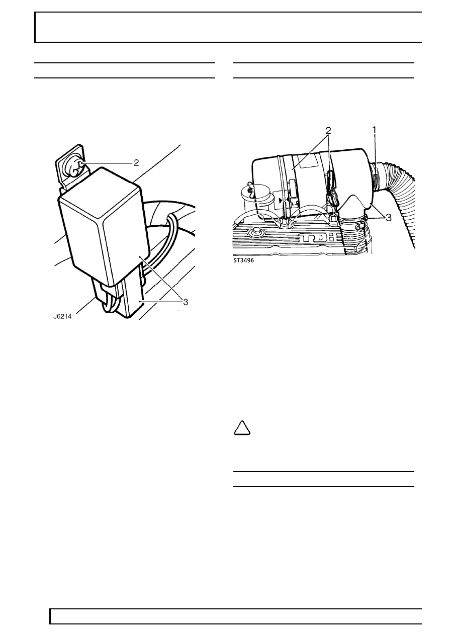
HEATER PLUG CONTROL UNIT

Service repair no - 19.60.33

Remove

1. Disconnect battery.

2. Remove screw securing control unit to bulkhead.
3. Disconnect multi-plug and release control unit.

Refit

4. Fit harness multi-plug to control unit.
5. Secure control unit to bulkhead.
6. Reconnect battery.

AIR CLEANER

Service repair no - 19.10.01

Remove

1. Slacken hose clip and detach outlet hose.
2. Release clips and open air cleaner retaining

straps.

3. Lift up air cleaner, slacken hose clip and detach

inlet hose.

4. Remove air cleaner.

Refit

5. Position air cleaner and connect inlet hose.
6. Close air cleaner retaining straps and secure

lock clips.

7. Connect outlet hose.

NOTE: If an EGR fuel system is fitted,
ensure the modulator valve vacuum spill
pipe is secure in the outlet hose.

AIR CLEANER ELEMENT

Service repair no - 19.10.10

For remove and refit procedure.

See SECTION 10,

Maintenance, Under bonnet maintenance

FUEL SYSTEM

13

REPAIR

THROTTLE CABLE

Service repair no - 19.20.06

Remove

1. Disconnect battery.

2. Remove split pin and clevis pin securing throttle

cable to injector pump throttle lever .

3. Depress ferrule retaining tags, release ferrule

from abutment bracket and withdraw throttle
cable.

4. Release throttle cable from clip on bulkhead.
5. Remove pin and clevis pin securing throttle

cable to pedal lever.

6. Release grommet from bulkhead.
7. Withdraw throttle cable from engine

compartment.

Refit

8. Feed throttle cable through bulkhead from

engine compartment and fit grommet.

9. Secure throttle cable to pedal lever. Use new

split pin to secure clevis.

10. Secure throttle cable in bulkhead clip.
11. Guide throttle cable through abutment bracket

and fit ferrule.

12. Secure cable to injection pump throttle lever.

Use new split pin to secure clevis.

13. Adjust throttle cable.

See Adjustment,

Throttle cable

THROTTLE PEDAL

Service repair no - 19.20.01

Remove

1. Remove throttle cable from pedal.

See Throttle

cable

2. Remove 6 bolts securing throttle pedal assembly

to engine bulkhead.

3. Remove pedal assembly from footwell, complete

with trim retainer.

4. Release return spring from pedal lever.
5. Remove roll pin securing pivot shaft to pedal

assembly.

6. Withdraw pivot shaft and remove pedal from

mounting bracket.

7. Remove return spring from pedal boss.

Refit

8. Fit return spring to pedal boss.
9. Fit pedal to mounting bracket and locate return

spring.

10. Fit pivot shaft to pedal assembly and secure with

roll pin.

11. Locate return spring on pedal lever.
12. Secure throttle pedal assembly and trim retainer

to bulkhead. Tighten bolts to

9 Nm (7 lbf/ft).

13. Fit throttle cable to pedal.

See Throttle cable

14. Adjust pedal, if necessary.

See Adjustment,

Throttle pedal adjustment

19

FUEL SYSTEM

14

REPAIR

TURBOCHARGER INLET HOSE

Service repair no - 19.42.11

Remove

1. Disconnect battery.

2. Slacken retaining clip and disconnect intake

hose from turbocharger.

3. Slacken retaining clip and disconnect hose from

air cleaner.

4. If fitted, disconnect EGR modulator valve

vacuum spill pipe from inlet hose.

5. Slacken retaining clip and disconnect breather

valve hose from inlet hose.

6. Remove inlet hose.

Refit

7. Fit inlet hose to air cleaner.
8. Fit cyclone breather hose to inlet hose.
9. If applicable, fit vacuum spill pipe to inlet hose.

10. Fit inlet hose to turbocharger.
11. Reconnect battery.

TURBOCHARGER OIL FEED PIPE

Service repair no - 19.42.14

Remove

1. Disconnect battery.
2. Remove exhaust front pipe.

See MANIFOLD

AND EXHAUST SYSTEM, Repair, Exhaust
front pipe

3. Remove banjo bolt securing oil feed pipe to

turbocharger and discard 2 joint sealing
washers.

4. Unscrew union and remove feed pipe from

cylinder block.

5. Plug connections to prevent ingress of dirt.

Refit

6. Using new joint washer, fit oil feed pipe to

cylinder block. Tighten union connector to

25

Nm (18 lbf/ft).

7. Fit a new joint washer to both sides of banjo and

secure feed pipe to turbocharger. Tighten banjo
bolt to

20 Nm (15 lbf/ft).

8. Fit exhaust front pipe.

See MANIFOLD AND

EXHAUST SYSTEM, Repair, Exhaust front
pipe

9. Check/top-up engine oil level.

See SECTION

10, Maintenance, Under bonnet maintenance

10. Reconnect battery.

FUEL SYSTEM

15

REPAIR

TURBOCHARGER OIL DRAIN PIPE

Service repair no - 19.42.12

Remove

1. Disconnect battery.
2. Remove exhaust front pipe.

See MANIFOLD

AND EXHAUST SYSTEM, Repair, Exhaust
front pipe

3. Unscrew union and disconnect oil drain pipe

from cylinder block.

4. Remove 2 bolts securing oil drain pipe to

turbocharger.

5. Remove drain pipe and discard gasket.
6. Plug connections to prevent ingress of dirt.

Refit

7. Ensure mating surfaces of oil pipe, turbocharger

and engine block are clean.

8. Using new gasket, fit oil drain pipe to

turbocharger. Tighten bolts to

25 Nm (18 lbf/ft).

9. Fit drain pipe to cylinder block and tighten union

connector to

38 Nm (28 lbf/ft).

10. Fit exhaust front pipe.

See MANIFOLD AND

EXHAUST SYSTEM, Repair, Exhaust front
pipe

11. Check/top-up engine oil level.

See SECTION

10, Maintenance, Under bonnet maintenance

12. Reconnect battery.


Content   ..  26  27  28  29   ..