Defender 300Tdi (1996+). Manual - part 27


  Index      Land Rover     Defender 300Tdi - service repair manual 1996 year


Search            


Content   ..  25  26  27  28   ..


Defender 300Tdi (1996+). Manual - part 27


19

FUEL SYSTEM

8

REPAIR

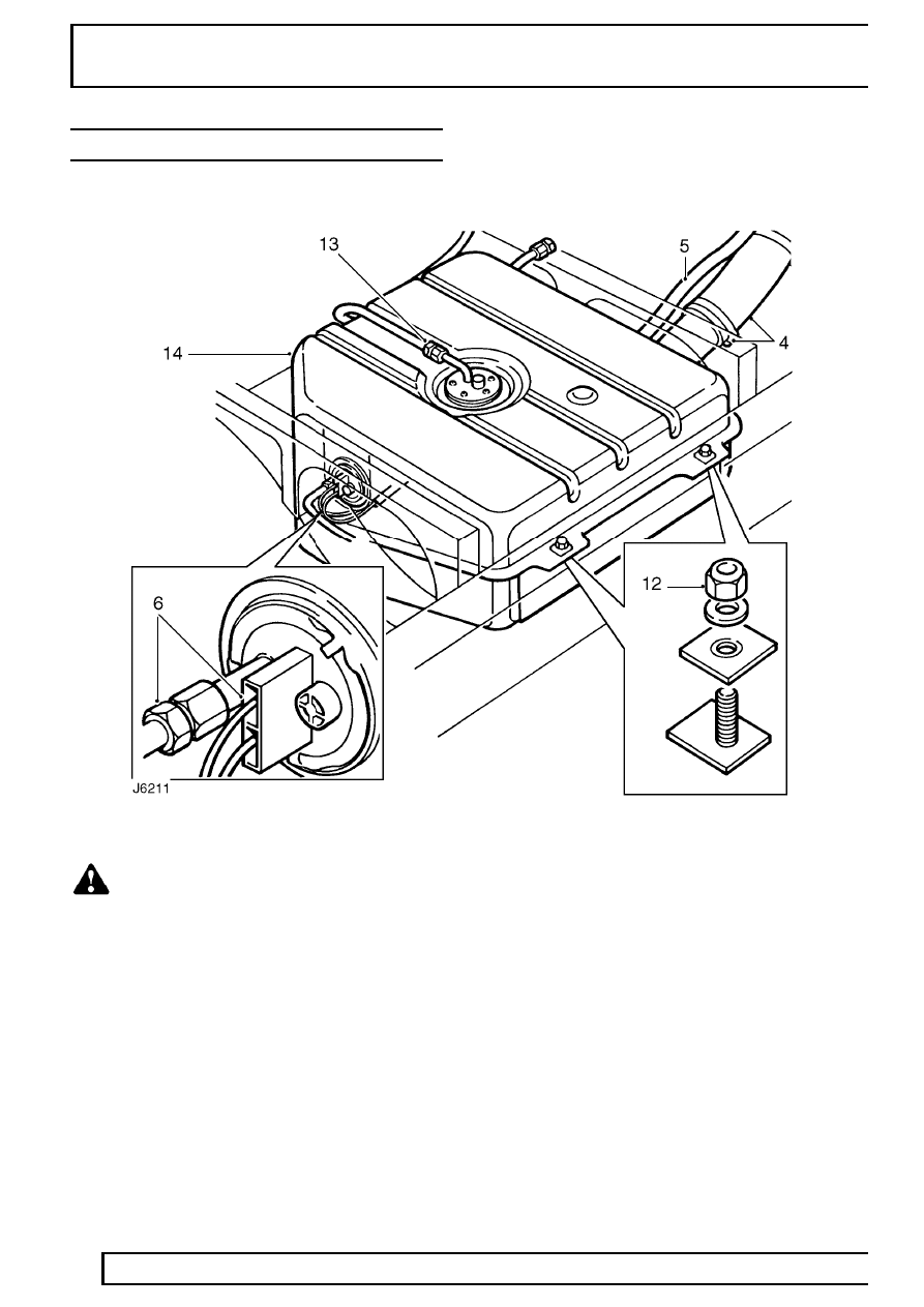
REAR MOUNTED FUEL TANK - 110/130

Service repair no - 19.55.26

WARNING: Before any attempt is made to
start the removal procedure it is vital that
the FUEL HANDLING PRECAUTIONS

See

INTRODUCTION, Information, FUEL HANDLING
PRECAUTIONS are carefully studied and
implemented in the interests of safety.

Remove

1. Disconnect battery.
2. Remove fuel filler cap.
3. Remove tank drain plug, allow fuel to drain into a

clean container, and refit plug.

4. Slacken retaining clips and disconnect fuel filler

hose from rear tank.

5. Disconnect breather hose from filler tube.
6. Disconnect electrical plug and fuel supply pipe

from outlet pipe union on fuel gauge unit.

7. If the vehicle is fitted with a tow ball drop-plate

with support bars, the bars must be removed.

8. Remove anti-roll bar chassis mountings.

See

REAR SUSPENSION, Repair, Anti-roll bar
and push roll bar down to provide access to the
tank.

9. Remove LH lashing eye to assist access to tank.

10. Position a support under the tank, preferably one

that can be progressively lowered.

FUEL SYSTEM

9

REPAIR

11. Remove 2 nuts that secure front fixing assembly

of the tank to chassis mounting bracket.

12. Remove tank rear mounting nuts.
13. With care, lower tank sufficiently to enable nut

and olive of spill return to be disconnected from
elbow in centre of tank.

14. Continue to lower tank until it can be removed

from vehicle.

NOTE: On later vehicles a separate stone
guard is fitted and is attached to the tank
with the existing front and rear fixings.

15. If required, remove tank gauge unit.

See

INSTRUMENTS, Repair, Fuel gauge tank unit
- side fuel tank 
or See INSTRUMENTS,
Repair, Fuel gauge tank unit - rear fuel tank,
110/130

Refit

16. If applicable, locate stone guard under tank.
17. Raise rear tank into position and connect spill

return pipe to the elbow with the nut and olive.

18. Continue to raise tank so that front and rear

mounting bolts locate in respective tank flange
holes.

19. Fit and tighten fixings to

20 Nm (15 lbf/ft).

20. Connect fuel suppnly pipe to the tank unit.
21. Fit fuel filler hose and breather pipe to filler tube

and secure with retaining clips.

22. Fit LH lashing eye to chassis.

23. Fit anti-roll bar chassis mountings.

See REAR

SUSPENSION, Repair, Anti-roll bar

24. Check that drain plug is secure and fill fuel tank.
25. Reconnect battery.
26. Prime fuel system.

See Adjustment, Priming

the fuel system and start engine.

27. Check system for leaks and operation of fuel

gauge.

19

FUEL SYSTEM

10

REPAIR

TWIN TANK CHANGE-OVER TAP ASSEMBLY

Service repair no - 19.43.50 - Fuel supply tap
Service repair no - 19.43.51 - Spill return tap
Service repair no - 19.43.52 - Fuel tank
change-over lever

Remove

1. Disconnect battery.
2. Remove RH front seat cushion.
3. Release retaining clip and remove access cover

from seat base.

4. Disconnect leads from fuel tank change-over

switch.

5. Unscrew retaining nut and withdraw change-over

lever and washers from pivot pin at heelboard.

6. Disconnect spill return pipes at spill change-over

tap.

7. Remove 4 bolts, washers and nuts securing tap

support bracket assembly to heel board.

8. Lift up support bracket assembly and disconnect

control rod from spill tap lever.

9. Remove support bracket assembly from vehicle.

10. Disconnect fuel supply pipes at fuel change-over

tap.

11. Remove 2 screws and release fuel tap from

chassis mounted support bracket.

12. Remove fuel tap, complete with operating rod

and lever.

13. Plug all connections to prevent ingress of dirt.
14. Dismantle spill return and fuel tap components

as necessary.

Refit

15. Fit fuel change-over tap, complete with operating

rod and lever, to chassis mounted support
bracket and fully tighten fixing screws.

16. Connect fuel supply pipes at fuel tap, ensuring

they are fitted to correct ports.

17. Position support bracket assembly behind

heelboard and connect operating rod to spill
change-over tap lever.

18. With pivot pin bush correctly seated, secure

support bracket assembly to heel board and
tighten fixings to

8 Nm (6 lbf/ft).

19. Connect spill return pipes to change-over tap,

ensuring they are fitted to correct ports.

20. Secure change-over lever to pivot pin.
21. Fit leads to fuel tank change-over switch.
22. Reconnect battery.
23. Prime vehicle fuel system,

See Adjustment,

Priming the fuel system if necessary and
check for leaks.

24. Fit access cover to seat base and seat cushion.

FUEL SYSTEM

11

REPAIR

HEATER PLUGS

Service repair no - 19.60.31

Remove

1. Disconnect battery.

No.1 heater plug - air conditioning models:

2. Release drive belt from compressor pulley.

See

AIR CONDITIONING, Repair, Compressor
drive belt

3. Remove 4 bolts securing compressor to front

cover, move compressor aside.

No.3 heater plug:

4. Remove retaining bolt and withdraw breather

valve from rocker cover. Remove and discard ’O’
ring.

All heater plugs:

5. Remove terminal nut and disconnect wire from

heater plug terminal.

6. Unscrew heater plug.

Refit

7. Clean heater plug and seating.
8. Coat threads of heater plug with suitable

anti-seize compound operational to a
temperature of 1000

°

C.

9. Fit heater plug, tighten to

23 Nm (17 lbf/ft).

10. Connect wire to heater plug terminal and secure

with nut.

NOTE: Feed wire must be connected to
No. 4 heater plug terminal.

No. 3 heater plug:

11. Lubricate new ’O’ ring with engine oil and fit to

breather valve.

12. Fit valve to rocker cover, tighten to bolt to

15 Nm

(11 lbf/ft).

No. 1 heater plug - air conditioning models

13. Position compressor to front cover, fit bolts and

tighten to

25 Nm (18 lbf/ft).

14. Fit drive belt to compressor pulley and adjust

tension.

See AIR CONDITIONING, Repair,

Compressor drive belt

All models:

15. Reconnect battery.


Content   ..  25  26  27  28   ..