Defender 90 NAS. Manual - part 93


  Index      Land Rover     Defender 90 NAS - service manual 1997 year


Search            


Content   ..  91  92  93  94   ..


Defender 90 NAS. Manual - part 93


AIR CONDITIONING

11

REPAIR

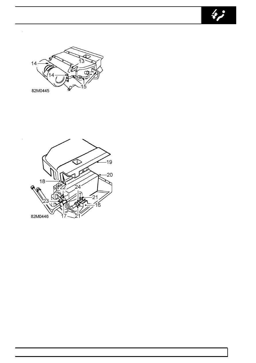
13. Remove screw securing mounting bracket flange

to casing.

14. Remove screws securing each end of blower

flanges to upper casing.

15. Remove 6 screws securing upper to lower

casing.

16. Remove tape sealing air duct inside casing.
17. Release tape sealing pipes to casing.
18. Cut through sealant along casing joint and

gaskets.

19. Ease upper from lower casing and remove upper

casing.

20. Lift evaporator unit from lower casing.

Do not

carry out further dismantling if component is
removed for access only.

21. Using a backing spanner, loosen union nut from

pipe and remove high pressure pipe. Discard ’O’
ring.

22. Loosen clip and withdraw capillary tube coil from

low pressure pipe and withdraw coil from pipe.

23. Loosen capillary tube union nut and disconnect

from low pressure pipe.Discard ’O’ ring.

24. Using a backing spanner, loosen union nut and

remove expansion valve from pipe. Discard ’O’
ring.

Refit

25. Lubricate NEW ’O’ rings with refrigerant oil and

fit to pipe ends.

26. Fit expansion valve to pipe, DO NOT tighten

union nut.

27. Connect capillary tube and tighten union nut.
28. Position capillary tube coil on low pressure pipe

and secure with clip.

29. Wrap capillary coil and union with prestite tape.
30. Connect high pressure pipe to expansion valve,

carefully align with low pressure pipe and tighten
union nut.

31. Tighten expansion valve union nut.
32. Position evaporator unit in lower casing, align

bracket and engage blower flange screws, DO
NOT tighten.

33. Position upper casing, engage lower casing

flange and secure with screws. Ensure mounting
bracket screw engages evaporator bracket.

34. Tighten blower flange screws.
35. Apply Silicone sealant to casing joint and

insulating tape to seal pipes to casing.

36. Apply sealing tape around air duct joint.
37. Position evaporator unit in footwell.
38. Connect multiplugs to compressor relays and

secure harness ’P’ clip.

39. Connect Lucars (G, U, and R) to resistor unit

and (B) to motor.

40. Lift evaporator, insert pipes into aperture and

engage mounting studs.

41. Connect drain tube to pipe.
42. Fit grommet into aperture.
43. Lubricate NEW ’O’ rings with refrigerant oil and

fit to

44. Carry out a functional check. joints.
45. Using a backing spanner, engage high pressure

pipe and tighten union nut.

46. Using a backing spanner, engage low pressure

pipe and tighten union nut.

47. Fit nuts and secure evaporator casing to

mounting bracket.

48. Fit fascia duct bezel.

See fascia duct bezel

49. Evacuate and recharge air conditioning system.

See Adjustment, refrigerant recovery
recycling recharging

50. Reconnect battery negative lead.
51. Perform leak test on disturbed joints
52. Carry out system test.

See Adjustment,

System test

82

AIR CONDITIONING

12

REPAIR

WIRING HARNESS - SUPPLEMENTARY

Service repair no - 86.70.23

Remove

1. Remove evaporator.

See evaporator

2. Remove nut and release earth eyelet from

fender.

3. Disconnect multiplug from compressor fly-lead.
4. Remove 4 ties securing harness to air

conditioning hoses.

5. Remove tie securing harness to engine harness.
6. Above chassis front crossmember, disconnect

multiplug from condenser fan fly-lead.

7. Disconnect multiplug from trinary switch.
8. Release ties securing harness to pipes.

9. Remove 4 screws securing fusebox cover to

centre console.

10. Remove cover.

11. Disconnect multiplug from main harness.
12. Remove screw securing earth eyelet to fusebox

bracket.

13. Pull harness from between centre console and

bulkhead.

14. Remove grommet from harness.
15. Remove ’P’ clip from harness.
16. Extract harness from front of engine

compartment and pass through bulkhead into
footwell area. Remove air conditioning harness.

AIR CONDITIONING

13

REPAIR

Refit

17. Position harness in footwell and route harness

into engine bay, follow evaporator and receiver
drier hoses to receiver drier.

18. Fit grommet and ’P’ clip to harness.
19. Position harness between centre console and

bulkhead with multiplugs in fusebox area.

20. Secure earth eyelet to fusebox bracket.
21. Connect multiplugs to main harness.
22. Position switch harness to RH side of console, fit

fusebox cover and secure with screws.

23. Connect multiplug to trinary switch and

condenser fan fly-lead.

24. Secure earth eyelet to fender.
25. Connect multiplug to compressor fly-lead.
26. Secure harness to air conditioning hoses with

ties.

27. Secure harness to engine harness with tie.
28. Fit evaporator.

See evaporator

29. Perform leak test on disturbed joints
30. Carry out system test.

See Adjustment,

System test

AIR CONDITIONING

1

SPECIFICATIONS, TORQUE

TORQUE VALUES

Air conditioning

Nm

lbf ft

Compressor to mounting bracket

25

.....................................

18

Compressor pipe flange bolts

10

..........................................

7

Receiver drier union bolts

6

................................................

4.5

Trinary pressure switch

11

....................................................

8

Pressure pipe union nuts - M16

14

.......................................

10

Discharge pipe union nuts - M22

22

.....................................

16

Suction pipe union nuts - M24

33

..........................................

24


Content   ..  91  92  93  94   ..