Defender 90 NAS. Manual - part 91


  Index      Land Rover     Defender 90 NAS - service manual 1997 year


Search            


Content   ..  89  90  91  92   ..


Defender 90 NAS. Manual - part 91


AIR CONDITIONING

3

REPAIR

RECEIVER DRIER

Service repair no - 82.17.01

Remove

CAUTION: If receiver drier is to be refitted,
the ports must be blanked off immediately
on disconnection. Exposed life of unit is

15 minutes.

1. Disconnect battery negative lead.
2. Recover refrigerant from system.

See

Adjustment, refrigerant recovery recycling
recharging

WARNING: Wear eye and hand protection
when disconnecting components
containing refrigerant.

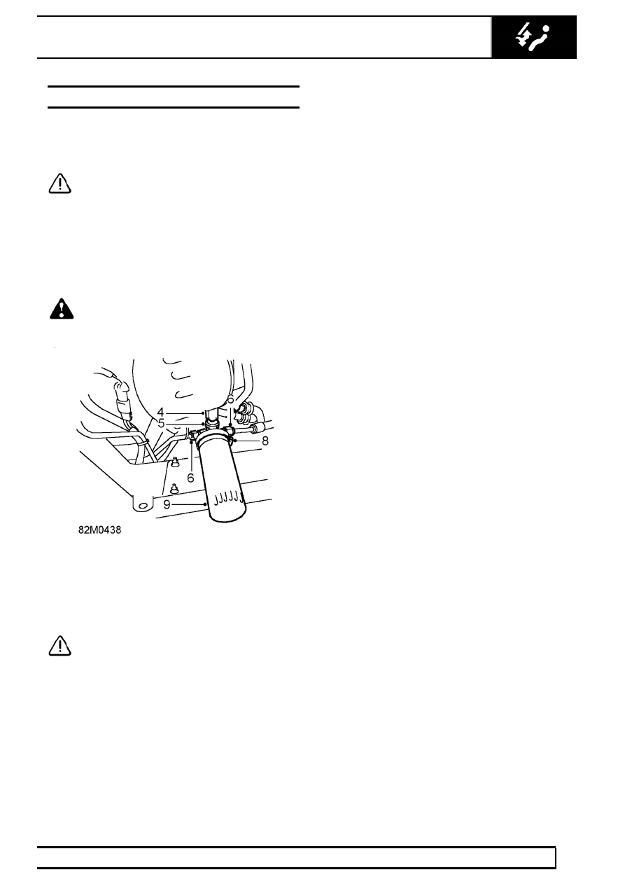
3. Clean area around receiver drier connections.
4. Disconnect multiplug from trinary switch.
5. Remove trinary switch from receiver drier.

CAUTION: Plug the connections.

6. Disconnect 2 pipe unions from receiver drier.
7. Remove and discard ’O’ rings from pipe flanges.
8. Fully loosen clip securing receiver drier to

bracket.

9. Remove receiver drier from clip.

Refit

10. Fit NEW ’O’ ring to each pipe flange, lubricate

with refrigerant oil.

11. Add 20ml, 0.7 fl oz of refrigerant oil to NEW

receiver drier.

12. Position receiver drier in clip, tighten clip but do

not clamp.

13. Engage pipes and tighten unions to

6 Nm, 4.5

lbf ft .

14. Fit trinary switch to receiver drier and tighten to

11Nm, 8 lbf ft.

15. Connect multiplug to trinary switch.
16. Tighten receiver drier clamp.
17. Evacuate and recharge air conditioning system.

See Adjustment, refrigerant recovery
recycling recharging

18. Perform a leak test on disturbed joints.
19. Carry out system test.

See Adjustment,

System test

82

AIR CONDITIONING

4

REPAIR

TRINARY PRESSURE SWITCH

Service repair no - 82.20.04

Remove

1. Disconnect battery negative lead.
2. Recover refrigerant from system.

See

Adjustment, refrigerant recovery, recycling,
recharging

3. Access below front RH of vehicle: Disconnect

multiplug from switch.

4. Remove switch from adaptor.

WARNING: Wear eye and hand protection
when disconnecting components
containing refrigerant.

5. Remove ’O’ ring from switch and discard.

Refit

6. Lubricate NEW ’O’ ring with refrigerant oil and fit

to switch.

7. Fit switch to adaptor and tighten to

11 Nm, 8 lbf

ft.

8. Connect multiplug.
9. Evacuate and recharge air conditioning system.

See Adjustment, Refrigerant recovery,
recycling, recharging

10. Reconnect battery negative lead.
11. Carry out system test.

See Adjustment,

System test

RELAY - FAN INTERLOCK

Service repair no - 82.20.08

Remove

1. Lever under each bottom corner and extract cold

air vents from bezel, 1 from LH side and 2 from
RH side.

2. Remove screw securing underside of bezel to

panel

3. Remove 3 screws securing inside of bezel to

panel

AIR CONDITIONING

5

REPAIR

4. Lift bezel away from evaporator casing
5. Withdraw capillary tube from evaporator fins.
6. Disconnect multiplug from fan interlock relay.
7. Remove securing screw and remove relay from

rear of bezel.

Refit

8. Fit screw and secure relay to rear of bezel.
9. Connect multiplug to fan interlock relay.

10. Position bezel assembly and insert capillary tube

60 mm, 2.5 in into evaporator fins.

11. Fit bezel assembly to panel and above

evaporator casing, secure with screws.

12. Fit cold air vents.
13. Carry out system test.

See Adjustment,

System test

RELAY - CONDENSER FAN

Service repair no - 82.20.09

Remove

1. Disconnect multiplug from relay.

NOTE: Connector wiring: B/S, N/P, N/S,
N/W

2. Release securing screw and remove relay from

side of evaporator casing.

Refit

3. Fit screw and secure relay to side of casing.
4. Connect multiplug to relay.
5. Carry out system test.

See Adjustment,

System test

82

AIR CONDITIONING

6

REPAIR

CONTROL SWITCHES

Service repair no - 82.20.10 - Temperature Control
Switch
Service repair no - 82.20.11 - Fan Switch

Remove

1. Remove fascia duct bezel.

See fascia duct

bezel

2. Pull control knobs from switches.
3. Remove switch panel.
4. Remove nut securing switch to bezel.
5. Remove switch.

NOTE: Fan switch to left.

Refit

6. Fit temperature control switch. Position capillary

tube inside duct to RH side.

7. Fit and tighten nut securing switch to bezel.
8. Fit switch panel.
9. Fit control knobs.

10. Fit fascia duct bezel.

See fascia duct bezel;

Refit

11. Carry out system test.

See Adjustment,

System test

RESISTOR UNIT

Service repair no - 82.20.26

Remove

NOTE: Access below evaporator unit.

1. Loosen outer screw securing resistor unit to

clamp.

2. Rotate resistor on motor.
3. Disconnect Lucars from resistor unit.

NOTE: Resistor wires: G, U, R and O

4. Remove screws securing resistor to clamp.
5. Remove resistor unit and clamp.

Refit

6. Position clamp over motor and place resistor,

terminals downward, onto motor.

7. Fit screws and tighten inner screw only.
8. Fit Lucars to resistor unit, in correct sequence.
9. Rotate resistor to fitted position and tighten outer

screw.

10. Carry out system test.

See Adjustment,

System test


Content   ..  89  90  91  92   ..