Defender 90 NAS. Manual - part 94


  Index      Land Rover     Defender 90 NAS - service manual 1997 year


Search            


Content   ..  92  93  94  95   ..


Defender 90 NAS. Manual - part 94


WIPERS AND WASHERS

1

REPAIR

WINDSCREEN WIPER MOTOR AND DRIVE RACK

Service repair no - 84.15.09
Service repair no - 84.15.12 - Wiper Motor

Remove

1. Disconnect battery.
2. Remove wiper arms.

See Windscreen wiper

arms

3. Remove fascia duct bezel.

See AIR

CONDITIONING, Repair, Fascia duct bezel

4. Remove screw securing door check strap cover.
5. Remove door check strap cover.

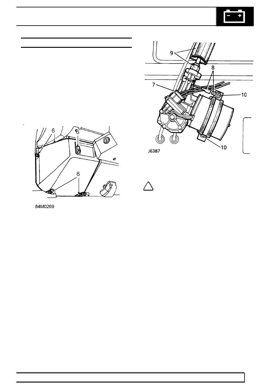
6. Remove 3 screws and withdraw wiper motor

cover. Disconnect instrument illumination switch
multi-plug.

7. Disconnect multi-plug from wiper motor.
8. Disconnect wiper motor earth lead. (Not

applicable on 97 MY vehicles).

9. Lift rubber sleeve and slacken wiper motor to

drive tube nut.

10. Remove 2 screws and release wiper motor

retaining strap.

11. Fully unscrew tube nut.
12. Pull wiper motor and drive rack clear of tube and

retrieve mounting pad and earth tag.

Do not carry out further dismantling if component
is removed for access only.

13. Remove 4 screws and lift off gearbox cover.
14. Remove circlip and small plain washer securing

connecting rod.

15. Remove connecting rod and disconnect drive

rack.

Refit

NOTE: Use Ragosine Listate Grease to
lubricate gear wheel teeth, connecting rod
pin and cable rack.

16. Ensure large flat washer is in place over

crankpin.

17. Connect drive rack to pin and fit connecting rod

over crankpin and secure with small plain
washer and circlip.

18. Fit gearbox cover and secure with screws.
19. Feed wiper motor drive rack into tube until fully

seated.

20. Loosely fit drive tube securing nut.
21. Fit wiper motor securing strap and mounting

pad. Align motor and tighten fixing screws.

22. Fully tighten tube nut and fit rubber sleeve.
23. Reconnect earth lead and multi-plug.
24. Fit wiper blades.

See Windscreen wiper arms

25. Reconnect battery and test operation of wiper

motor and drive assembly. If necessary, adjust
position of wiper blades.

26. Fit instrument illumination switch multi-plug.
27. Fit cover and door check strap cover.
28. Refit fascia duct bezel.

See AIR

CONDITIONING, Repair, Fascia duct bezel

84

WIPERS AND WASHERS

2

REPAIR

WINDSCREEN WIPER ARMS

Service repair no - 84.15.01

Remove

1. Pull wiper arm away from windscreen.
2. Using a small screwdriver, hold back spring clip

which retains arm to spindle adaptor.

3. Pull wiper arm from splined adaptor.

Refit

4. Switch wiper motor to ’park’ position, with grub

screw retaining adaptor, uppermost.

5. Push arm on to adaptor ensuring that wiper

blade is just clear of windscreen surround
rubber.

6. Operate wipers and, if necessary, adjust position

of arms.

WINDSCREEN WIPER/WASHER SWITCH

Service repair no - 84.15.34

For remove and refit procedure

See ELECTRICAL,

Repair, Windscreen wiper/washer switch

REAR SCREEN WIPER AND WASHER SWITCHES

Service repair no - 84.30.27 - Rear Screen Washer
Switch
Service repair no - 84.35.33 - Rear Screen Wiper
Switch

For remove and refit procedure

See ELECTRICAL,

Repair, Heated rear screen, rear wiper and washer
switches

WIPERS AND WASHERS

3

REPAIR

WINDSCREEN WIPER WHEEL BOXES

Service repair no - 84.15.25

Remove

1. Disconnect battery.
2. Remove wiper arms.

See Windscreen wiper

arms

3. Remove wiper motor and drive rack.

See

Wiper motor and drive rack

4. Remove instrument housing, fascia crash pad,

and ventilator grille panel.

5. Slacken steering column support rod lower

fixing.

6. Remove steering column upper support fixing.
7. Slacken nuts to release back plates from LH and

RH wheel boxes.

8. Remove drive rack tubes.
9. Slacken grub screws and remove wiper arm

adaptors.

10. Remove LH and RH wheelbox spindle nuts.
11. Remove wheel box assemblies from vehicle.

84

WIPERS AND WASHERS

4

REPAIR

Refit

NOTE: During reassembly, all fixings
related to wiper motor and wheelboxes are
finger tightened only, until all components

are correctly aligned.

12. Fit wheelboxes to bulkhead and secure with

retaining nuts and washers.

13. Fit drive rack tubes to wheelboxes.
14. Apply grease to drive rack and wheelboxes.
15. Align wiper motor and mounting pad, secure with

retaining strap and tighten drive tube nut.

16. Fully tighten wheelbox back plate nuts.
17. Fully tighten both wheelbox spindle nuts.
18. Fit wiper arm adaptors and secure with grub

screw.

19. Before refitting panels fit wiper blades, connect

multi-plug and ground lead, reconnect battery
and check wiper operation.

20. If satisfactory, secure steering column upper and

lower fixings and tighten to correct torque.

21. Fit ventilator grille panel, fascia crash pad,

instrument housing and all other components
removed to gain access to wiper motor and
wheelboxes.

REAR WIPER MOTOR

Service repair no - 84.35.12

Remove

1. With assistance, unscrew 3 retaining nuts and

remove spare wheel from rear door mounting
studs.

2. Lift wiper arm end cap to gain access to securing

nut.

3. Remove nut and withdraw wiper arm from drive

spindle.

4. Remove retaining nut, plain washer and rubber

washer securing wiper motor drive spindle to
door.

5. Remove 2 screws and remove cover from wiper

motor mounting bracket.

6. Disconnect wiper motor harness multi-plug.
7. Remove bolt, with rubber washer, and remove

wiper motor from rear door.


Content   ..  92  93  94  95   ..