Defender 90 NAS. Manual - part 81


  Index      Land Rover     Defender 90 NAS - service manual 1997 year


Search            


Content   ..  79  80  81  82   ..


Defender 90 NAS. Manual - part 81


76

CHASSIS AND BODY

22

REPAIR

REAR HEADLINING - HARD TOP

Service repair no - 76.64.11

Remove

1. Remove rear end trim panel.

See Rear end

trim panel - hard top

2. Remove side trim panels.

See Side trim panel

- hard top

3. Remove rear grab handles.

See Rear grab

handle - hard top

4. Remove rear end lining.

See Rear end lining

hard top

5. Remove rear interior lamp.

See ELECTRICAL,

Repair, Interior lamp

6. Remove interior roll-over bar.

See Interior

roll-over bar - hard top

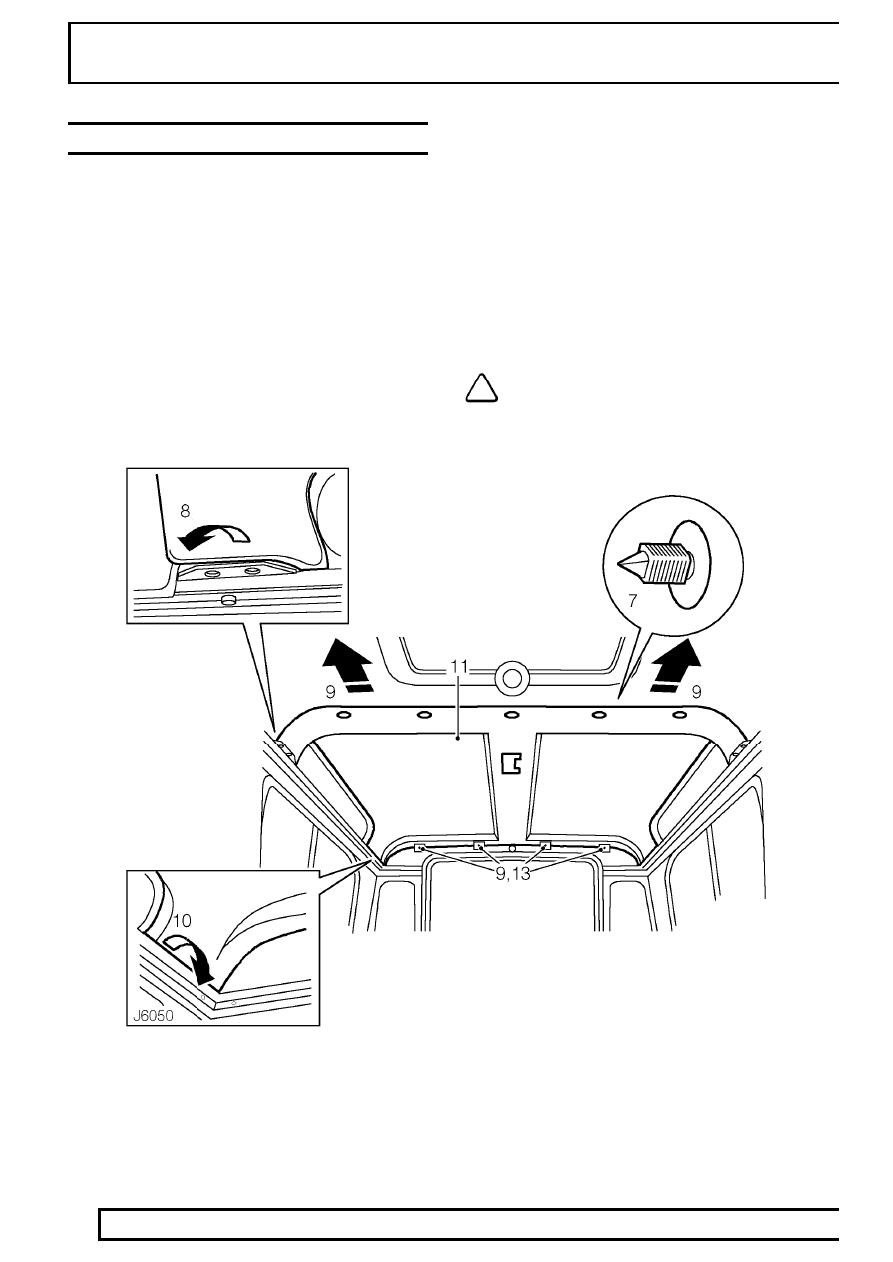
7. Carefully prise out 7 trim studs securing rear and

front headlining to roof mounting brackets.

8. Release front corners of headlining from cant

rail, on both sides.

9. Pull headlining forwards sufficiently to clear rear

end lining mounting brackets.

10. Release rear corners of headlining from cant rail,

on both sides.

11. Lower rear headlining from roof and remove

from vehicle.

NOTE: Take care not to bend headlining
on removal and refitting.

CHASSIS AND BODY

23

REPAIR

Refit

12. With assistance, position rear headlining to roof

and locate rear corners in cant rail.

13. Push headlining rearwards and position over

rear end lining mounting brackets.

14. Locate front corners of headlining in cant rail.
15. Position front edge of rear headlining over front

headlining and secure with trim studs.

16. Adjust rear headlining to achieve good fit at all

corners.

17. Fit rear interior lamp.

See ELECTRICAL,

Repair, Interior lamp

18. Fit interior roll-over bar.

See Interior roll-over

bar - hard top

19. Fit rear end lining.

See Rear end lining - hard

top

20. Fit rear grab handles.

See Rear grab handle -

hard top

21. Fit side trim panels.

See Side trim panel -

hard top

22. Fit rear end trim panels.

See Rear end trim

panel - hard top

BONNET LOCK

Service repair no - 76.16.21

Remove

1. Open bonnet.

2. Mark position of guide plate and lock to bonnet

platform.

3. Remove 8 screws securing grille.
4. Remove grille.
5. Remove 2 bolts securing guide plate and lock.
6. Remove guide plate.
7. Release spring securing lock to bonnet platform.
8. Slacken clamping bolt securing bonnet release

cable.

9. Remove lock.

Refit

10. Fit spring between lock and bonnet platform.
11. Position lock and guide plate to bonnet platform

and nip up bolts.

12. Position guide plate and lock to position marks

and tighten bolts to

10 Nm. 7 lbf/ft.

13. Fit cable to lock and tighten clamping bolt.
14. Check operation of release cable and adjust if

necessary.

15. Fit grille and tighten securing screws.
16. Close bonnet.

76

CHASSIS AND BODY

24

REPAIR

BONNET RELEASE CABLE

Service repair no - 76.16.29

Remove

1. Open bonnet.
2. Remove 8 screws securing grille.
3. Remove grille.

4. Slacken clamping bolt securing bonnet release

cable.

5. Remove cable from lock.
6. Release cable from clip on underside of bonnet

platform.

7. Feed cable through valance.
8. Collect cable grommet.
9. Loosen clamping nut securing bonnet release

pull to mounting bracket.

10. Remove bonnet release pull from mounting

bracket.

11. Withdraw cable through bulkhead.

Refit

12. Feed cable through bulkhead and fit bonnet

release pull to mounting bracket. Tighten
clamping nut.

13. Route cable along inner wing.
14. Feed cable through valance.
15. Fit grommet between cable and valance.
16. Fit cable to securing clip on underside of bonnet

platform.

17. Fit cable to lock and tighten clamping bolt.
18. Check operation of release cable and bonnet

lock and adjust if necessary.

19. Fit grille and tighten screws.
20. Close bonnet.

CHASSIS AND BODY

25

REPAIR

LOWER FASCIA PANEL (HEATER DUCT)
ASSEMBLY

Service repair no - 76.46.05

Remove

1. Disconnect battery.
2. Remove steering wheel. If necessary, use puller

LRT-57-014.

3. Remove 7 screws and lift lift top half of nacelle

from steering column switch assembly.

4. Ease bottom half of nacelle from switch

gaiters/grommets and remove.

5. Remove instrument panel.

See INSTRUMENTS,

Repair, Instrument panel

6. Disconnect heater control cable.

See HEATING

AND VENTILATION, Repair, Heater control
cable - air distribution

7. Prise out Land Rover decal and remove screw

securing grab handle to crash pad.

8. Remove screw securing grab handle to lower

fascia panel.

9. Lift grab handle to release locating pins from

fascia panel.


Content   ..  79  80  81  82   ..