Defender 90 NAS. Manual - part 8


  Index      Land Rover     Defender 90 NAS - service manual 1997 year


Search            


Content   ..  6  7  8  9   ..


Defender 90 NAS. Manual - part 8


GENERAL FITTING REMINDERS

3

INFORMATION

BALL AND ROLLER BEARINGS

CAUTION: Never refit a ball or roller
bearing without first ensuring that it is in a
fully serviceable condition.

1. Remove all traces of lubricant from bearing

under inspection by washing in a suitable
degreaser; maintain absolute cleanliness
throughout operations.

2. Inspect visually for markings of any form on

rolling elements, raceways, outer surface of
outer rings or inner surface of inner rings. Reject
any bearings found to be marked, since any
marking in these areas indicates onset of wear.

3. Holding inner race between finger and thumb of

one hand, spin outer race and check that it
revolves absolutely smoothly. Repeat, holding
outer race and spinning inner race.

4. Rotate outer ring gently with a reciprocating

motion, while holding inner ring; feel for any
check or obstruction to rotation, and reject
bearing if action is not perfectly smooth.

5. Lubricate bearing generously with lubricant

appropriate to installation.

6. Inspect shaft and bearing housing for

discoloration or other marking suggesting that
movement has taken place between bearing and
seatings. (This is particularly to be expected if
related markings were found in operation 2).

7. Ensure that shaft and housing are clean and free

from burrs before fitting bearing.

8. If one bearing assembly of a pair shows an

imperfection it is generally advisable to replace
both with new bearings; an exception could be
made if the faulty bearing had covered a low
mileage, and it could be established that
damage was confined to it only.

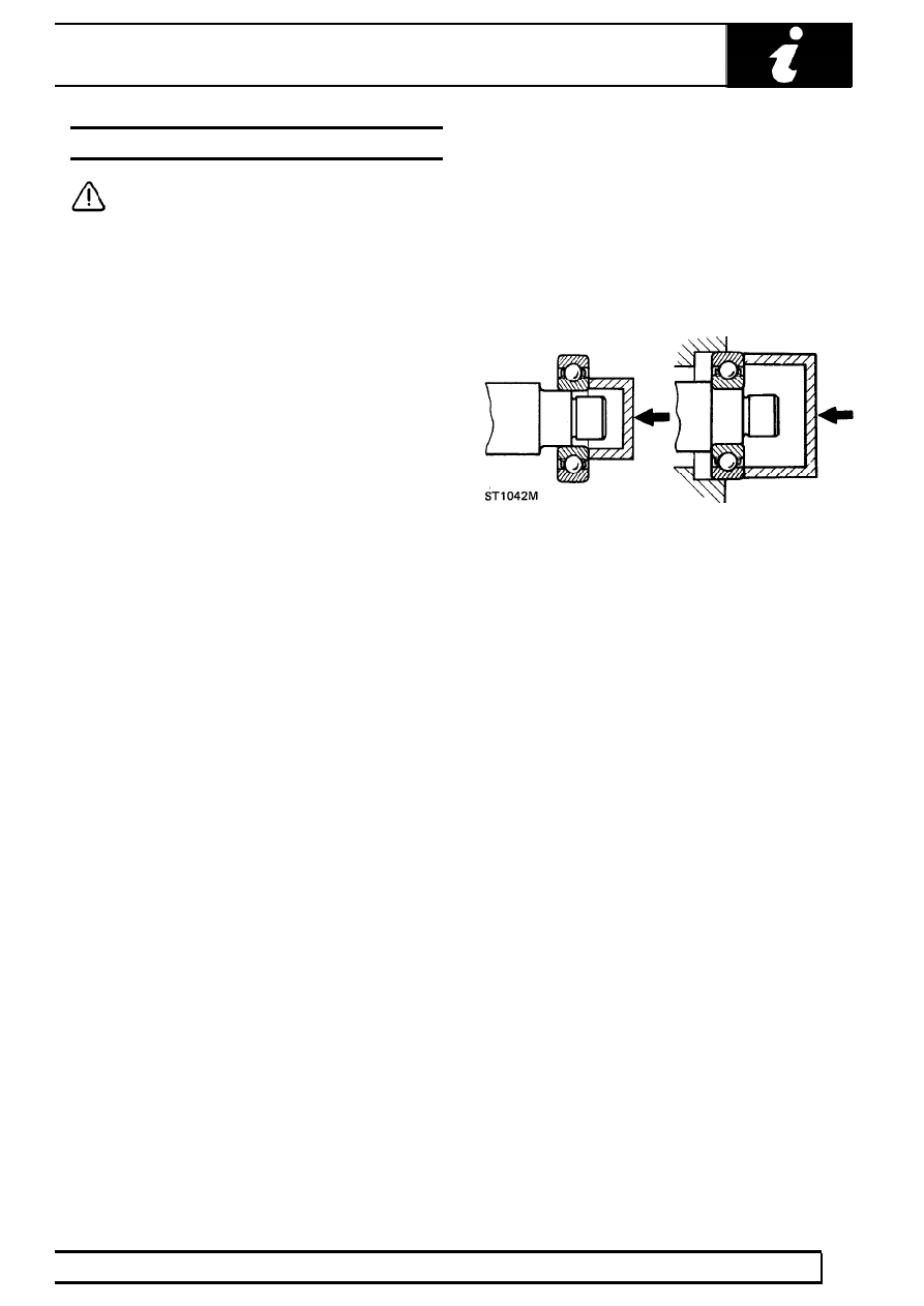
9. When fitting bearing to shaft, apply force only to

inner ring of bearing, and only to outer ring when
fitting into housing.

10. In the case of grease lubricated bearings (e.g.

hub bearings) fill space between bearing and
outer seal with recommended grade of grease
before fitting seal.

11. Always mark components of separable bearings

(e.g. taper roller bearings) in dismantling, to
ensure correct reassembly. Never fit new rollers
in a used outer ring, always fit a complete new
bearing assembly.

07

GENERAL FITTING REMINDERS

4

INFORMATION

OIL SEALS

NOTE: Ensure that the seal running track
is free from pits, scores, corrosion and
general damage prior to fitting

replacement seal.

1. Always fit new oil seals when rebuilding an

assembly.

2. Carefully examine seal before fitting to ensure

that it is clean and undamaged.

3. Coat the sealing lips with clean grease; pack

dust excluder seals with grease, and heavily
grease duplex seals in cavity between sealing
lips.

4. Ensure that seal spring, if provided, is correctly

fitted.

5. Place lip of seal towards fluid to be sealed and

slide into position on shaft, using fitting sleeve
when possible to protect sealing lip from damage
by sharp corners, threads or splines. If fitting
sleeve is not available, use plastic tube or tape
to prevent damage to sealing lip.

6. Grease outside diameter of seal, place square to

housing recess and press into position, using
great care and if possible a ’bell piece’ to ensure
that seal is not tilted. (In some cases it may be
preferable to fit seal to housing before fitting to
shaft). Never let weight of unsupported shaft rest
in seal.

7. If correct service tool is not available, use a

suitable drift approximately 0.4mm (0.015 in)
smaller than outside diameter of seal. Use a
hammer VERY GENTLY on drift if a press is not
suitable.

8. Press or drift seal in to depth of housing if

housing is shouldered, or flush with face of
housing where no shoulder is provided. Ensure
that the seal does not enter the housing in a
tilted position.

NOTE: Most cases of failure or leakage of
oil seals are due to careless fitting, and
resulting damage to both seals and

sealing surfaces. Care in fitting is essential if
good results are to be obtained. NEVER use a seal
which has been improperly stored or handled,
such as hung on a hook or nail.

GENERAL FITTING REMINDERS

5

INFORMATION

JOINTS AND JOINT FACES

1. Always use correct gaskets where they are

specified.

2. Use jointing compound only when

recommended. Otherwise fit joints dry.

3. When jointing compound is used, apply in a thin

uniform film to metal surfaces; take great care to
prevent it from entering oilways, pipes or blind
tapped holes.

4. Remove all traces of old jointing materials prior

to reassembly. Do not use a tool which could
damage joint faces.

5. Inspect joint faces for scratches or burrs and

remove with a fine file or oil stone; do not allow
removed material or dirt to enter tapped holes or
enclosed parts.

6. Blow out any pipes, channels or crevices with

compressed air, fit new ’O’ rings or seals
displaced by air blast.

FLEXIBLE HYDRAULIC PIPES, HOSES

1. Before removing any brake or power steering

hose, clean end fittings and area surrounding
them as thoroughly as possible.

2. Obtain appropriate plugs or caps before

detaching hose end fittings, so that ports can be
immediately covered to exclude dirt.

3. Clean hose externally and blow through with

airline. Examine carefully for cracks, separation
of plies, security of end fittings and external
damage. Reject any hose found faulty.

4. When refitting hose, ensure that no unnecessary

bends are introduced, and that hose is not
twisted before or during tightening of union nuts.

5. Containers for hydraulic fluid must be kept

absolutely clean.

6. Do not store brake fluid in an unsealed

container. It will absorb water, and fluid in this
condition would be dangerous to use due to a
lowering of its boiling point.

7. Do not allow brake fluid to be contaminated with

mineral oil, or use a container which has
previously contained mineral oil.

8. Do not re-use brake fluid bled from system.
9. Always use clean brake fluid to clean hydraulic

components.

10. Fit a cap to seal a hydraulic union and a plug to

its socket after removal to prevent ingress of dirt.

11. Absolute cleanliness must be observed with

hydraulic components at all times.

12. After any work on hydraulic systems, inspect

carefully for leaks underneath the vehicle while a
second operator applies maximum pressure to
the brakes (engine running) and operates the
steering.

07

GENERAL FITTING REMINDERS

6

INFORMATION

FUEL SYSTEM HOSES

CAUTION: All fuel hoses are made up of
two laminations, an armoured rubber outer
sleeve and an inner viton core. If any of

the fuel system hoses have been disconnected, it
is imperative that the internal bore is inspected to
ensure that the viton lining has not become
separated from the amoured outer sleeve. A new
hose must be fitted if separation is evident.

METRIC BOLT IDENTIFICATION

1. An ISO metric bolt or screw, made of steel and

larger than 6 mm in diameter can be identified by
either of the symbols ISO M or M embossed or
indented on top of the head.

2. In addition to marks to identify the manufacture,

the head is also marked with symbols to indicate
the strength grade, e.g. 8.8, 12.9 or 14.9, where
the first figure gives the minimum tensile
strength of the bolt material in tens of kgf/mm

2

.

3. Zinc plated ISO metric bolts and nuts are

chromate passivated, a gold-bronze colour.

METRIC NUT IDENTIFICATION

1. A nut with an ISO metric thread is marked on

one face or on one of the flats of the hexagon
with the strength grade symbol 8, 12 or 14.
Some nuts with a strength 4, 5 or 6 are also
marked and some have the metric symbol M on
the flat opposite the strength grade marking.

2. A clock face system is used as an alternative

method of indicating the strength grade. The
external chamfers or a face of the nut is marked
in a position relative to the appropriate hour
mark on a clock face to indicate the strength
grade.

3. A dot is used to locate the 12 o’clock position

and a dash to indicate the strength grade. If the
grade is above 12, two dots identify the 12
O’clock position.

KEYS AND KEYWAYS

1. Remove burrs from edges of keyways with a fine

file and clean thoroughly before attempting to
refit key.

2. Clean and inspect key closely; keys are suitable

for refitting only if indistinguishable from new, as
any indentation may indicate the onset of wear.

TAB WASHERS

1. Fit new washers in all places where they are

used. Always fit a new tab washer.

2. Ensure that the new tab washer is of the same

design as that replaced.


Content   ..  6  7  8  9   ..