Defender 90 / 110 / 130. Manual - part 205
T
RANSM
I
S
S
IO
N
Mainshaft and gears clearance checks.
Running clearances
'
Mainshaft 1st gear
Mainshaft 3rd gear
Mainshaft 5th gear
shaft bearing
maximum
maximum
maximum
maximum
Third gear end-float.
Locate t h e mainshaft in a vertical position
as
shown. Fit t h e third
roller
bearing
and spacer t o t h e mainshaft and replace t h e
synchromesh inner
down on t h e synchromesh inner member and
check the gear running clearance with a feeler
clearance in excess
of
indicates that the thrust faces are
worn and may b e the cause
of
gear noise o r
transmission back-lash. New
or
little worn
components will usually have a clearance
of
between
and
to
Second gear end float
Invert the mainshaft f o r assembly
of
t h e rear
end components.
3. Fit t h e s e c o n d gear needle
roller
bearing,
spacer, Second gear and synchromesh inner
member. Press down on the synchromesh
inner member and check t h e second gear e n d
float which
is
t h e same
as
the third gear
previously described.
I
4.
Remove t h e synchromesh inner member and
assemble
it
t o the outer member with the
slippers, balls and springs.
5. Fit the second gear baulk ring to t h e mainshaft
and the first and s e c o n d synchromesh hub
with the selector groove towards the rear end
of
the
items
to
1 7 mainshaft
page 6.
to
bush
end-float.
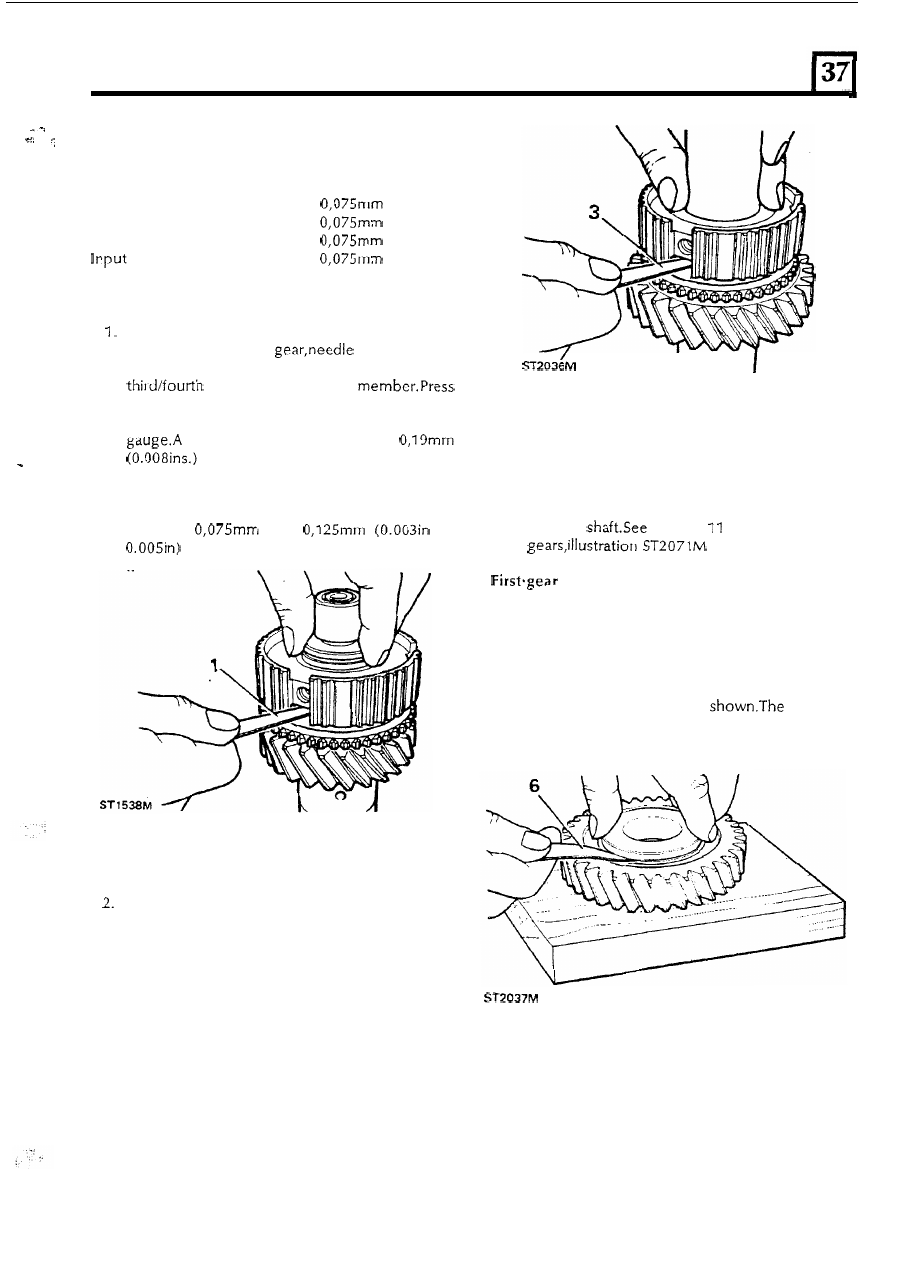
6 .
To
carry-out the first gear check, d o not
assemble the components t o t h e mainshaft.
Assemble t h e spacer, needle bearing and bush
t o the first gear and using a suitable straight
e d g e or flat plate, check the end float of 'the
first gear o n the bush,
as
tolerance
is t h e same
as for
t h e third and second gears.
21