Defender 90 / 110 / 130. Manual - part 196
STEERING
15.
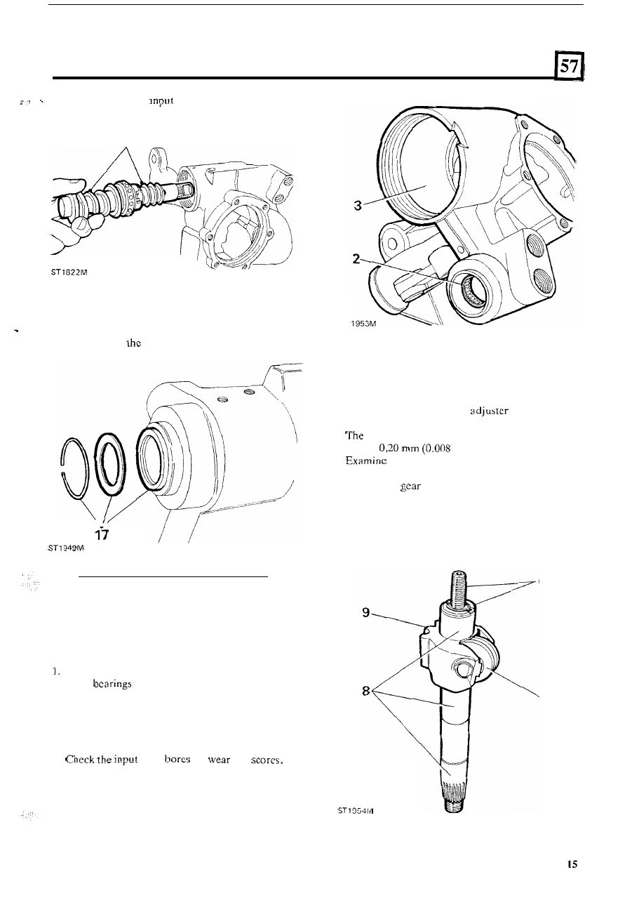
Withdraw the
shaft, worm and valve
assembly.
15
16.
Release the circlip and remove the steel washer
and oil seal from the sector shaft housing.
oil seal from
input shaft housing.
17.
Remove the wire circlip, anti-extrusion washer and
INSPECTION AND OVERHAUL OF COMPONENTS
Steering box housing
2
3 .
4
Examine the sector shaft upper and lower needle
roller
and if necessary drive them from the
housing with a suitable drift.
Inspect the input shaft needle bearing and if worn
drive
it
from the housing and press-in a
replacement.
Examine the piston bore for wear and scores.
shaft
for
and
ST
Sector shaft assembly
5 .
Chcck that no side play or wear exists in the roller.
6. Check the condition of the
and its retainer
7.
axial clearancc of
t h e
adjustcr should not
8.
the bearing journals o n the shaft for wear
9. Check the
teeth for excessive and uncvcn
and that the crimping
is
sound.
exceed
in).
and damage.
wear, scores and pitting.
continued