Defender 90 / 110 / 130. Manual - part 197


  Index      Land Rover     Defender 90 / 110 / 130 - service repair manual


Search            


Content   ..  195  196  197  198   ..


Defender 90 / 110 / 130. Manual - part 197


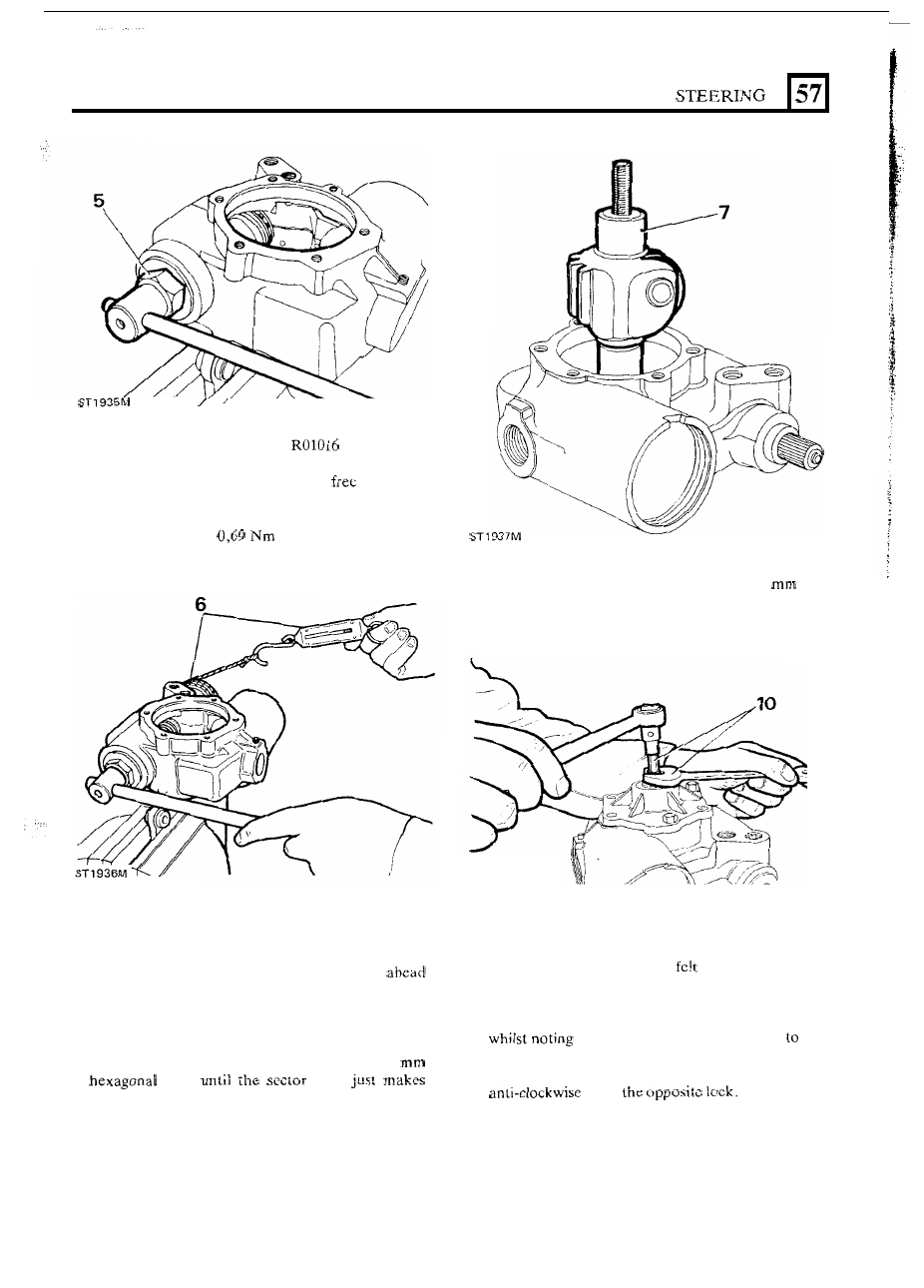
6.  Secure  preload  setting  tool 

to  the  input 

shaft  with  the  grub  screw.  Wind  string  round  the 
tool  and  tie  a spring balance to the 

end of  the 

string.  Whilst  turning  the  input  shaft  cover 
clockwise,  pull  the  spring balance  until  a constant 
preload reading 

of 

is achieved. 

Fitting sector shaft and piston-rack assembly 

7. 

Fit  the  sector  shaft  to  the  housing  and  engage  it 

with  the  input  shaft  worm  in  the  straight 
position. 

8. 

Screw-on,  to  the  sector  shaft  adjuster,  the  sector 

shaft cover and  secure with  two or three of  the six 
retaining screws. 

9.  Turn  the  adjuster  screw  clockwise,  with  a  6 

key, 

shaft 

contact with the input shaft worm. 

10.  Without moving  the adjuster, f i t  the locknut whilst 

restraining  the  adjuster  screw  with  the 

key 

and  just  nip  the  locknut  with  an  open-ended 
spanner. 

ST 1938M 

11. 

Temporarily 

fit 

the  drop  arm  and  tighten  the 

locknut until no clearance is 

between  the sector 

shaft and drop arm. 

12. 

Rotate  the  input  shaft  one  turn  clockwise,  then 
turn  the  shaft back  to  the  straight  ahead  position 

the point  at which  the backlash 

the 

drop arm disappears 

or 

is ‘taken-up’. 

on to 

13.  Repeat  instruction  12  and  rotate  the  input  shaft 

19 

S

TEERING 

18.  Lubricate the rack  piston  plastic seal and insert the 

piston  into  the  piston  bore,  rack  end  first,  as  in 
instruction 

of  the  dismantling  procedure, 

to  a 

depth of 37 

below the lip 

of  the bore. 

19.  Lubricate  and  fit  the  sector  shaft  in  the  straight 

ahead position. 

20.  Lubricate  and  f i t  

ring  seal 

to  the  sector  shaft 

cover. 

21.  Restrain  the sector shaft adjuster and screw-on 

cover, reversing instruction  17. Secure 

with 

the six 

bolts,  tightening  evenly  to  25 

to 

30 

(18 

to 

22  Ibs  ft). 

22.  Restrain  the  sector  shaft  adjuster  and 

fit 

and 

tighten the locknut, as instruction  10. 

23. 

Fit 

and  lubricate  an 

ring 

to  the  rack 

adjuster screw. 

24. 

Fit  the  rack  pad  and  spring noting  that  the  larger 
flat side of  the pad is towards 

rack. 

If  the  difference between  the  two  points  at  which 

the  backlash  is  ‘takcn-up’ or  disappears 

is  greater 

than 

90” 

a turn) 

it 

will be necessary to change 

the shimming  behind  the input  shaft inner  bearing 

cup. 

15.  If  the shimming requires adjustment, add a shim on 

right-hand  drive  steering  boxes  if  backlash  starts 
too quickly on clockwise rotation. Should backlash 

start 

too 

quickly  for  anti-clockwise  rotation, 

remove a shim. For a left-hand  drive steering box, 
reverse the foregoing procedure. 

NOTE: 

If 

it  is 

necessary to perform instruction  15, 

instructions 

to 

13 

must be repeated afterwards. 

Remove  the  drop  arm  and  whilst  restraining  the 

sector  shaft  adjuster,  so  that  it  does  not  turn, 
remove the locknut. 

17. 

Remove  the  sector  shaft  cover  screws  and  while 

ST 1944M 

25.  Screw-in  the  rack  pad  adjuster  until  the  head 

from 

steering box face. 

still  restraining  the  adjuster,  unscrew  clockwise, 
the  cover  from  the  sector  shaft  and  withdraw  the 
sector shaft. 

20 

S

TEERING 

. . 

26.  Lubricate and fit an 

ring seal to the piston-rack 

cover. 

27.  Fit  the  piston  cover  t o   steering  box.  Align  the 

retaining  ring hole  in  the cover with  the cut-out  in 

steering box  housing and 

hooked end of  the 

retaining  ring 

in  the  hole.  Using  special  tool 

rotate the cover anti-clockwise  to feed the 

ring  into  the  groove  until  the  ring  is  fully  seated, 

This is a reversal  of  instruction 3 

of  the dismantling 

procedure. 

28.  Temporarily  fit  the  drop arm  and 

with  the 

nut  so that  no backlash  is present between 

arm 

and  sector  shaft. 

Set 

the  steering 

in 

the  straight 

ahead position. 

29.  Fit  the  preload  setting  tool 

to 

the  input 

shaft  and  secure  with  the  grub  screw.  Rotate  the 
input  shaft  in  both  directions  clockwise  and  anti- 
clockwise 

to 

o f  

a  turn  to check  the  backlash 

distribution. 

30.  To  check 

drop  arm  angular  travel  for  a 

LHD 

drive  steering  box  use  the  prcload  setting  tool  to 

turn 

the  input  shaft  two  turns  clockwise  and  one 

and  three-quarter  turns  anti-clockwise. 

For  RHD 

drive boxes, 

opposite applies. 

3 1.  Remove the drop arm. 
32.  Return to the straight ahead position  and screw the 

rack  adjuster  clockwise  until 

adjuster  pad  just 

contacts the pad. 

21 

N G  

STEER 

Fitting input shaft 

seal 

36.  Using  the  three  part tool 

lubricate  a  new 

seal  and  slide  it,  lip  side  leading, over  the  conical 
seal-savcr to the detachable lower part of  the tool. 

36 

37,  Withdraw  the  conical  seal-saver  and  place  the 

lower  part  of  the  tool  with  the  seal,  lip  side 
downwards, over the input shaft. 

38. 

Place  the seal-driver part 

of  the  tool on top of  the 

seal and drive 

i t  

fully home. 

39.  Fit  the  anti-extrustion  washer  and  secure  the 

assembly with the wire circlip. 

Fitting sector shaft 

oil 

seal 

40.  Lubricate  the  oil  seal  and  seal-saver 

41.  Using the seal-driver part of the tool, push  the seal 

slide the seal over the tool, lip side leading. 

fully home into the housing. 

42. 

Fit  the  steel  washer  and  secure  the  assembly 

with 

the circlip. 

22 


Content   ..  195  196  197  198   ..