Defender 90 / 110 / 130. Manual - part 194
F
U
EL SYSTEM
59.
Assemble the jet to the bi-metal jet lever and
ensure that the jet head moves freely in the
cut-out.
60.
Fit the jet and bi-metal jet lever to the carburetter
and secure with the spring loaded jet retaining
screw.
61. Fit the mixture adjusting screw.
19
.
62. Adjust the mixture screw until the jet is flush with
the carburetter bridge, then turn the screw a
further three and one half turns clockwise.
63. Using
a new sealing ring, fit the float chamber
cover, noting that it can only be fitted o n e way.
Secure with the four screws and spring washers and
evenly tighten.
Fit piston
and
suction
chamber
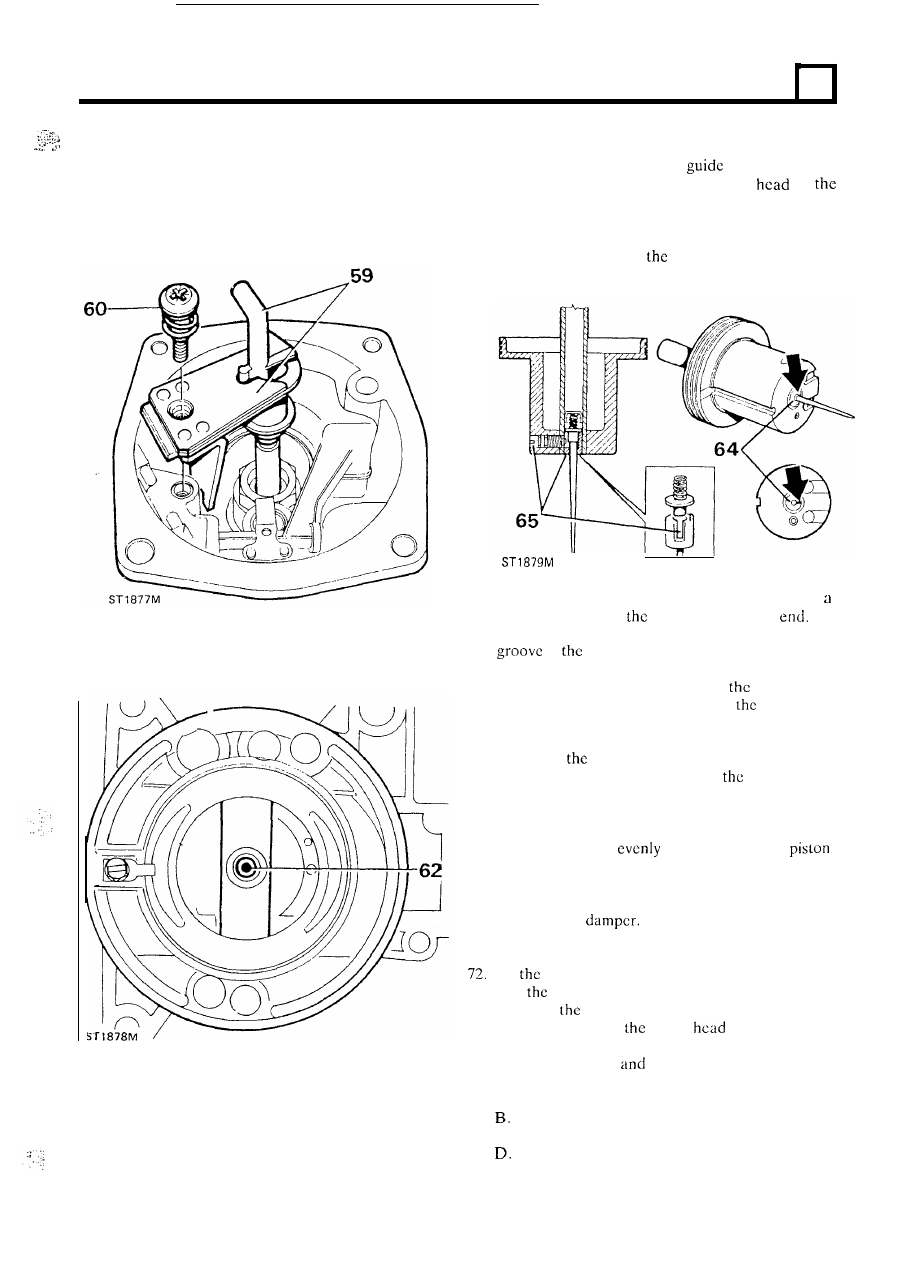
64.
Fit the needle, spring and
assembly to the
piston ensuring that the etched arrow
on
needle locating guide is aligned between
t h e
piston
transfer holes, as illustrated.
65. Secure and ensure that when
the
screw is tightened
the guide is flush with
piston and that the screw
locates in the guide slot.
I
I
66. Fit the piston key to the carburetter body using
new screw. Tighten
scrcw and splay
t h e
67. Fit a new suction chamber sealing ring
to the
in
carburetter body.
68. To
prevent the piston spring being ‘wound-up’
during assembly, temporarily
fit
piston
and
suction chamber less the spring to
body, and
pencil mark the relationship of the chamber to the
body. Kcmove the suction chamber and
fit
the
spring to
piston. Hold the suction chamber
above the spring and piston, align
pencil marks
and lower the chamber over the spring and piston,
taking care not to rotate the suction chamber.
Secure the chamber to the body with the three
screws, tightening
and check that the
moves freely.
69. Hold the piston at t h e top of its stroke and
fit
the
spring clip.
70.
Fit
t h e
piston
71.
Using a new joint washer, fit
t h e
air
intake adaptor
and secure with the two nuts and spring washcrs.
Fit
carburetters to the inlet manifold ensuring
that
joint washers, dcflcctor and insulator are
fitted in
sequence illustrated. The insulator
must be fitted with
arrow
uppermost and
pointing inwards towards the manifold. Secure
with the four nuts
spring washers and tighten
eveniy
to
the correct torque.
A .
Joint washer.
Deflector-teeth pointing inwards.
C.
Joint washer.
Insulator.
E. Joint washer.
continued
7