Defender 90 / 110 / 130. Manual - part 170
DEFENDER
ENGINE
Fitting connecting
rods and pistons
1.
Ensure that the essentric headed big end bolts
and shell bearings are correctly located in the
connecting
rods and as a precaution against
possible damage t o the crankshaft journals
during installation
of the pistons, cover the
bolt threads with a layer
of
adheasive tape.
Check that the number o n the connecting rod
is
the same
as the piston and cylinder and that
they are correctly orientated.
2.
With the cylinder block vertical, and
2
and
crankshaft journals at BDC lubricate and install
and
3
piston connecting rod assemblies
so
that the piston rings are resting o n the block
face.
illustrated, then using a suitable tool compress
the piston rings and gently push each piston
4.
Pull both connecting rod big ends on t o the
journals and fit the caps ensuring the the
numbers match and orientation
is
correct.
Retain the caps with new nuts but
d o not
tighten at this stage.
at BDC and install t h e pistons and connecting
rods as previously discribed.
the correct torque and check that the
crankshaft is free t o rotate before securing the
next connecting rod cap nuts.
which when tightened restricts the freedom
of
the crank shaft.
sideways o n its journal and
if
necessary check
the actual
side
clearance using a feeler gauge.
The correct clearance is given in the data
section.
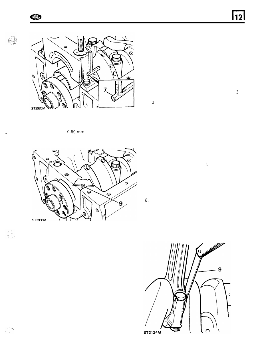
9.
To allow
for
shrinkage after fitting leave the
3.
Stagger the piston rings on both pistons
as
seals standing proud
of the crankcase face
then using a sharp blade, trim the seals
off to
face.
approximately
above the crankcase
into the cylinder bore.
5.
Tum the crankshaft so that
and
4
journals are
7.
Tighten both nuts
on
o n e connecting rod
to
Investigate and rectify any big end bearing
9.
Check that each big e n d
is
free to move
59