Defender 90 / 110 / 130. Manual - part 169
DEFENDER
ENGINE
. -
11.
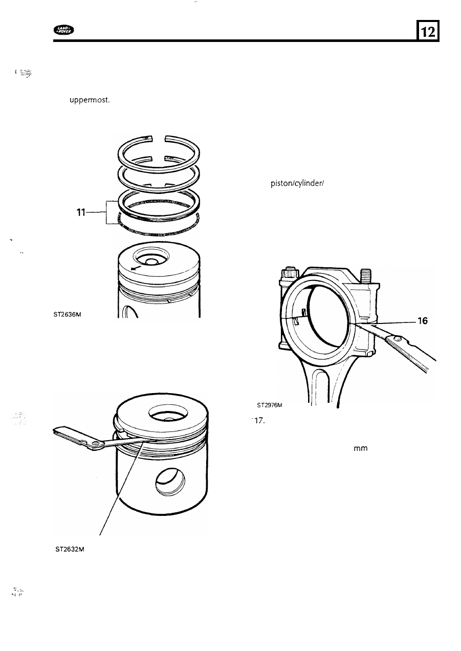
Fit
the oil control ring expander t o the bottom
groove, then fit the
oil control ring ensuring
that it fits over the expander. Fit the second,
narrow, compression ring with the word "TOP"
Likewise fit the first compression
ring to the top groove, word
"TOP"
uppermost.
.
..
.
12. After fitting slide each ring around the groove
to ensure that it is free and does not bind.
13. Using an appropriate feeler gauge check the
groove clearance between the rings and
piston.
I f
the clearances in excess
of the
figures given in data section the rings or the
pistons should b e renewed.
Gudgeon pins
14. Examine the g u d g e o n pin for obvious wear,
cracks, scores,
or
overheating and ovality and
taper using a micrometer.
Connecting
rods
15. Check the connecting rods and caps for
distortion as follows; fit the correct cap, less
the bearing shells, t o each connecting rod
as
denoted by the number stamped near the joint
faces. This number
also indicates the
crankshaft journal t o which it
must
be fitted.
16.
Tighten both nuts t o the correct torque, then
release o n e nut o n each cap, now check that
n o clearance exists a t the joint face as
illustrated.
A
clearance may indicate a bent bolt
o r that either
of the joint faces has been filed
o r machined previously, in attempt t o rectify
excessive bearing wear.
I
Use an accurate connecting rod alignment
gauge t o check t h e rods for bend and twist.
The maximum allowable for both conditions
must not
exceed 0,127
(0.005
in).
18.
Examine and check the small-end bush for
wear.
If
necessary renew the bush. The correct
clearance
of
t h e gudgeon pin in the small-end
bush
is given in t h e data section.
in the bush lines u p with the hole in the
connecting rod. Finish the bush t o the correct
size and clearance.
19.
When renewing a bush ensure that the oil hole
13
. .
.
...
.
..
55