Defender 90 / 110 / 130. Manual - part 167


  Index      Land Rover     Defender 90 / 110 / 130 - service repair manual


Search            


Content   ..  165  166  167  168   ..


Defender 90 / 110 / 130. Manual - part 167


ENGINE 

DEFENDER 

Removing f u e l  p u m p  a n d  side cover 

20. 

Use 

key t o  release  the fuel  lift 

pump t o  gain  access 

to 

the side cover 

retaining  bolts. 

21. 

Release the 

six 

bolts  and remove  the cover 

plate. 

See fitting  l i f t  pump. 

Remove  front s i d e  cover plate 

22. 

Release the six  bolts  and remove  the front side 

cover plate  complete with  the crankcase 

ventilation  pipe. 

Remove  camfollowers 

See 

cylinder h e a d   remove 

CAUTION: 

T h e  camfollers  a r e  solid  rollers 

held  in  position against t h e  cam  by  a slide 
inside  a fixed guide. 

If 

t h e  guide 

is removed 

before  t h e  roller,  it 

is possible  that t h e  

roller c a n  fall  behind  t h e  camshaft  a n d  
b e c o m e  jammed.  Furthermore  t h e  roller 
could slip p a s t  t h e  cam  a n d  fall  into t h e  
crankcase. 

I t  

is t h e r e f o r e  important  t o  adopt 

t h e  following  p r o c e d u r e  for removal. 

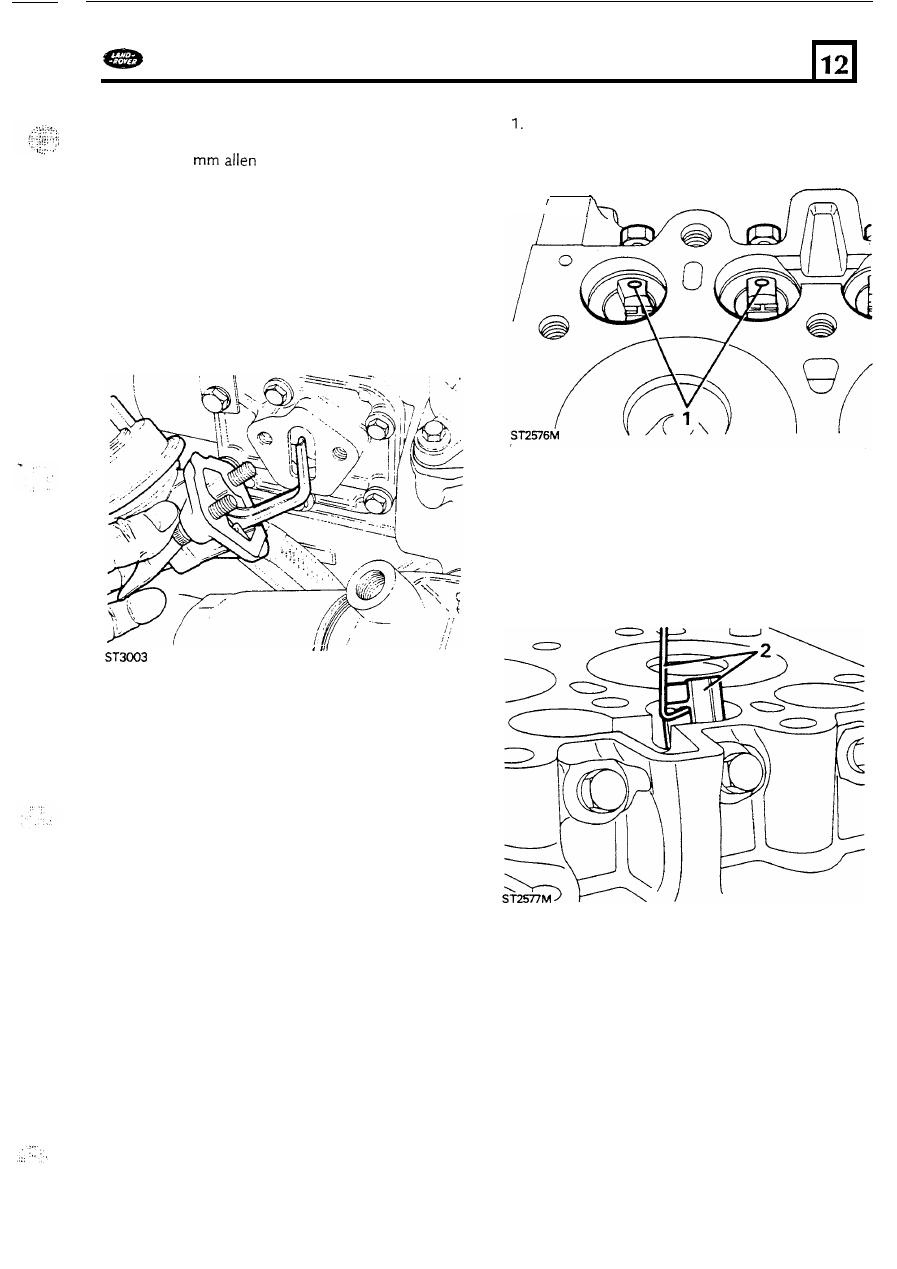
Slacken  back  the guide locating  screw 

so that 

the end is  below the bore 

of  the guide. 

2. 

Using  a length 

of thin  wire with  a hooked  end 

3. 

With  the same piece 

of  wire  remove  the roller 

4. 

Remove  the guide locating  screw and lift-out 

6 .  

As 

each assembly is  removed  number it,  from 

lift-out the slide. 

the guide. 

o n e  to eight, 

for 

refitting  t o  its original 

location. 

See 

fitting cam followers 

47 

Removing the  camshaft. 

ENGINE 

DEFENDER 

Release 

the two screws and remove  the 

camshaft thrust  plate. 
Carefully Withdraw the camshaft  taking  care 
not 

to allow the end of  the shaft  to drop o n  t o  

the bearings 

as 

it  is  removed. 

See fitting  camshaft 

Removing  Clutch and  Flywheel  housing 

See 

1. 

2 .  

See 

engine unit  removal 

Mark  the relationship 

of  the cover t o  the 

flywheel  t o  ensure original  balance 

is 

maintained. 
Evenly slacken  and  remove  the six retaining 
bolts  and washers  and  remove the assembly 

complete with  the friction  plate. 

fitting clutch 

Removing flywheel 

In  the  intrests 

of  safety, fit 

two 

long 

bolts 

into the clutch  bolt  holes,  diametrically 
opposite, t o  use 

as 

handles for lifting  the 

flywheel 

off  the  crankshaft. 

temporarily  fit  the the crankshaft damper and 
use special service  tool 

FR 

t o  restrain  the 

crankshaft while  slackening the flywheel  eight 
retaining  bolts.  Remove the bolts and 
reinforcing  plate  and lift-off  the flywheel. 

See 

overhaul  and fitting flywheel 

Removing  flywheel  housing. 

1. 

Remove the eight internal  and two external 

and  five  ladder frame  securing  bolts,  then  ease 
the flywheel  housing  from  the 

two 

locating 

dowels and  crankshaft. 

See 

fitting rear main 

oil  seal 

to 

flywheel  housing. 

A 8  

... 

DEFENDER 

ENGINE 

Removing  s u m p  a n d  oil  p u m p  

If 

necessary  drain  the engine oil. When 

working  with  t h e  engine on a work stand, 
invert  the cylinder block 

so that  the sump is 

uppermost.  Remove t h e  screws and ease the 
sump from t h e  ladder frame t o  reveal the oil 

Note:  After  removing  t h e  oil  s u m p  when t h e  

engine  is  in  t h e  vehicle,  refit  a n d  tighten 

two 

of  t h e  retaining bolts  t o  t h e  left side of 

t h e  cylinder 

block to maintain  pressure  o n  

t h e  l a d d e r  f r a m e  cylinder  block  joint seal. 

See 

fitting s u m p  

Removing 

p u m p  

Two 

bolts secure the oil  pump t o  the 

crankcase. Access 

to the right  hand  bolt  may 

require t h e  u s e  

of  a socket with  a universal 

joint.  Removal 

of  the two  bolts will  enable the 

pump t o  b e  withdrawn. 

See fitting oil  p u m p  

Removing  ladder frame 

Note:  The ladder f r a m e  a n d  flywheel 

housing are s e c u r e d  by  five  bolts which  are 
inaccessable with  t h e  gearbox bell housing 
fitted. Therefore 

it 

is  n o t  possible  t o  remove 

t h e  ladder frame w h e n  t h e  e n g i n e  is  in  t h e  
vehicle without  first removing t h e  gearbox 
or 

engine unit,  flywheel flywheel  housing, 

engine sump a n d  

oil 

p u m p  

3. 

With  the engine removed, release t h e  
remaining  ten  bolts and separate the ladder 
frame  from  the crankcase by  gently  tapping 

to 

break  the seal. 

See 

fitting ladder frame 

49 

ENGINE 

DEFENDER 

Removing pistons and connecting rods 

Note: On this version 

of  the Tdi  engine, 

it 

is  not 

possible t o  remove the connecting rods or 
pistons with  the engine in  the vehicle because 

of 

the method by  which  the ladder frame is secure. 
See note under Ladder  frame  removal. 

Turn  the crankshaft t o  bring  all  the connecting 

rod  cap nuts t o  an accessable  position  and 

slacken  t h e  nuts  using  a 

socket. 

2. 

Remove t h e  connecting rod  nuts and remove 

t h e  caps complete with  lower bearing  halves. 

3. 

Before  removing  the piston  assemblies, 
number each piston  from 

one 

t o  four 

so that it 

can  b e  identified  with  the bore from  which  it 
was  removed. 

4. 

Taking  care not t o  damage the bores, push 

each connecting  rod  and  piston,  in  turn,  up 
t h e  bore until 

it 

can  b e  withdrawn  from  the 

cylinder 

block  combustion face. 

As 

each  piston 

assembly is  removed  fit  the corresponding cap 
and  bearing  shell 

to the connecting rod  noting 

that t h e  shell  locating  tags are together o n  the 
same side as the connecting  rod  number. 

See piston  and connecting rods 

Removing  crankshaft. 

Slacken the ten  mainbearing  bolts with  a 

socket. 

2. 

If 

difficulty 

is  experienced removing  t h e  cap a 

suggested method is  t o  

lever 

t h e  cap from 

both 

sides, as  illustrated. 

3. 

Insert  a  suitable bar  in  t h e  hole  in  the inside 

face 

of 

t h e  cap and lever against the crankshaft 

journal  o n  the outside 

face.  Ensure that  blocks 

of  timber  are used  under t h e  levers particularly 
t o  protect  the crankshaft. 

mainbearing  caps complete with  the lower 
bearing  shells. 

4. 

Release  the remaining  bolts  and  remove t h e  

5 0  


Content   ..  165  166  167  168   ..