Defender 90 / 110 / 130. Manual - part 142
Warning Light
at stand-still.
extinguished at cut-in
( I
but
at
higher speeds
becomes
illuminated again
and gets progressively brighter
Not illuminated
zero
at
,500
High
High
A L T E R N A T O R
DOES N O T C H A R G E
WEAK O R
C H A R G E
O V E R C H A R G E
WORN O R SLACK B E L T
WORN O R DIRTY B R U S H E S
BROKEN O R FAULTY R O T O R WINDING
B R E A K IN C H A R G I N G C I R C U I T
OPEN CIRCUIT
OK
F A U L T Y
D I O D E
FAULTY R E G I J L A T O R
2
OR
3
D I O D E S
P O L A R I T Y F A U L T Y
W O R N O R SLACK B E L T
WORN O R DIRTY B R U S H E S
O N E O R M O R E D E F E C T I V E RECTIFIER D I O D E S
FAULTY R E G U L A T O R
FAULTY CONNECTIONS
FAULTY R E G U L A T O R
FAULTY CONNECTIONS B E T W E E N A L T E R N A T O R A N D R E G U L A T O R
OPEN
OR SHORT-CIRCUITED
ELECTRICAL
EQUIPMENT
-
ALTERNATOR
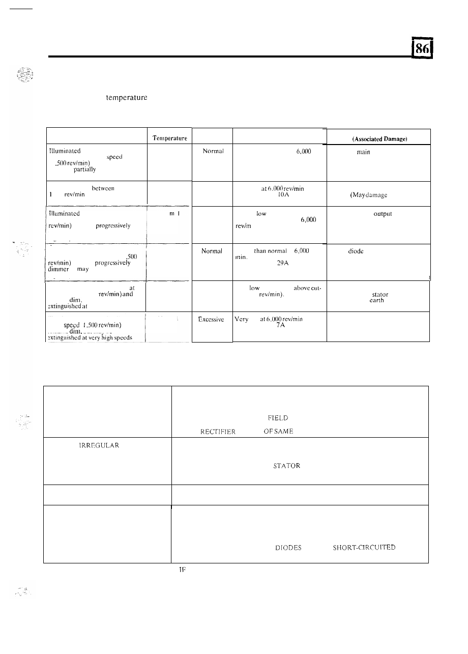
DIODE FAULT SYSTEM
Failure
of one or more of the diodes
will
be indicated by the output
of the alternator and in
some
instances by an
abnormally high
and noise level. The following fault symptom chart shows how diode failure will
influence alternator test results.
Noise
Probable
Fault
o u t p u t
Higher than normal
at
revimin.
Approximately 40A
Live-side
output diode open
circuit. (May damage rotor field
winding and regulator, overheat,
brushboxes. and fuse warning
light bulb)
Excessive
Very low
Approximately
Live-side main
output
diode short
circuit.
associated
'field' diode)
Excessive
Poor at
speed
Slightly below normal at
in.
Approximately 32A
Earth-side main
diode
open circuit
at
stand-still, dims
appreciably
at
cut-in speed
( I ,500
and gets
dimmer o r
may
be extinguished
at
higher speeds
Nor
a I
'Field'
open-circuit
Illuminated
at
stand-still. dims
appreciably at cut-in speed ( I
and gets
or
be extinguished
a t
higher speeds
Normal
Lower
a t
rev/
Approximately
I
Excessive
Very
at
all
speeds
i n
(1.500
Illuminated at stand-still. dims
Gut-in speed (1,500
remains
but may he
very high speeds
Normal
Earth-side main output diode
short-circuit, o r
winding
short-circuit
t o
'Field' diode short-circuit
low
Approximately
Illuminated
at
stand-still, dims a t
:ut-in
(
a n d
remains
but
may
be
Normal
ALTERNATOR FAULT AND DIAGNOSIS CHART
NOISY ALTERNATOR
WORN B E L T
LOOSE PULLEY
LOOSE ALTERNATOR MOUNTINGS
MISALIGNMENT O F PULLEYS
FAULTY BEAKING
O N E
OR S E V E R A L RECTIFIER
O P E N O R
SHORT-CIRCUITED S T A T O R
i
CHECK EACH ITEM IN T U R N AND RECTIFY
NECESSARY B E F O R E P R O C E E D I N G
TO N E X T ITEM.
29