Defender 90 / 110 / 130. Manual - part 140
ELECTRICAL EQUIPMENT -
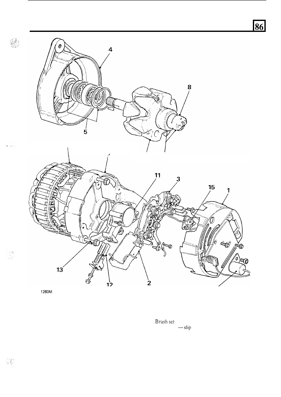
ALTERNATOR
ST
10
9
1. Cover
2. Regulator
3. Rectifier
4. Drive-end bracket
5. End bearing
kit
6.
Rotor
assembly
7. Slip ring end bearing
8. Slip rings
6
7
14
KEY
TO ALTERNATOR
9. Slip ring end bracket
10. Stator
11. Brush box
12.
13. Fixing bolt
ring end bracket to drive-end bracket
14. Suppression capacitor
15. Surge protection diode
21