Defender 90 / 110 / 130. Manual - part 111
STEERING
34. Drive-in a new bearing, up to the shoulder, with
the bearing number and chamfered ends of the
rollers trailing.
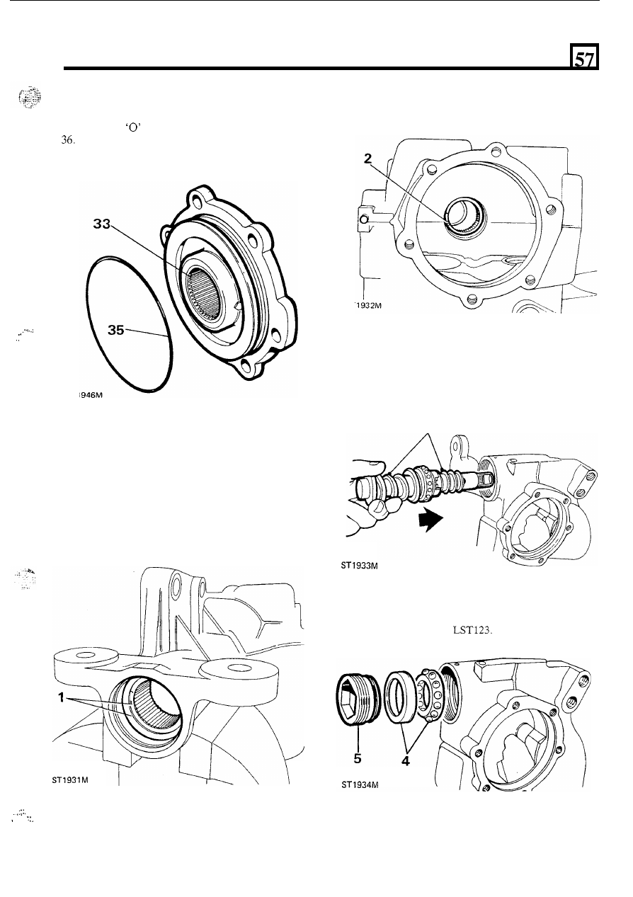
35. Fit a new
ring seal
to the cover.
Check that the cover bearing lubrication passage
and bleed nipple hole
is clear.
.
.
. . .
...
,
ST
1
2.
Fit the sector shaft upper needle bearings, number
outwards, up to the shoulder.
ST
Fitting the valve and worm assembly (input shaft)
3. Fit the input shaft to the steering box housing and
lubricate with the recommended fluid. Turn the
shaft to the straight ahead position.
Assemble
3
During the following assembly instructions absolute
cleanliness must be observed.
Also
when fitting
components and oil seals they must only be lubricated
with the recommended fluid, or petroleum jelly.
1. If removed, fit the sector shaft lower needle
bearings, numbers outwards, to the steering box to
just below the chamfer.
4.
Fit the input shaft outer bearing and track.
5.
Lubricate and fit the input shaft cover and
‘0’
ring
seal using special tool
..
.,.
.
.
. I .
,
,
.....
37