Defender 90 / 110 / 130. Manual - part 49


  Index      Land Rover     Defender 90 / 110 / 130 - service repair manual


Search            


Content   ..  47  48  49  50   ..


Defender 90 / 110 / 130. Manual - part 49


CYLINDER ENGINE 

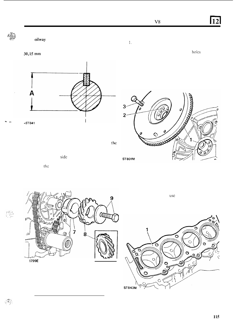
CAUTION: The space between the key and keyway acts 
as  an 

for  lubrication  of  the  drive  gear.  Ensure 

that the key is seated 

to the full depth of the keyway. The 

overall  dimension 

of  shaft  and  key  must  not  exceed 

(1.187 in). Dimension A below. 

FIT THE FLYWHEEL 

Locate  the  flywheel 

in  position  on  the  crankshaft 

spigot, with the ring gear towards the engine. 

2.  Align  the  flywheel  fixing  bolt 

which  arc 

off-set to prevent incorrect assembly. 

3 .  

Fit  the  flywheel  fixing  bolts  and  before  finally 
tightening,  take  up  any  clearance  by  rotating 

the 

flywheel  against  the  direction 

of  engine  rotation. 

Tighten the bolts evenly to the correct torque. 

7. 

Check  that  the  timing  marks  line-up  and  fit 

spacer with the flange to the front. 

8.  Fit  the  distributor  drive  gear  ensuring  that  the 

annular  grooved 

is  fitted  to  the 

rear,  that  is 

towards the spacer. 

9. 

Secure 

drive  gear  and  camshaft  chain  wheel 

assembly  with  the 

bolt 

and  washer  and  tighten  to 

the correct torque. 

FIT 

CYLINDER 

HEADS 

1. 

Fit  new  cylinder head gaskets 

with 

the word 

‘TOP’ 

uppermost. 

Do NOT 

sealant. 

continucd 

RR 

V8 CYLINDER 

ENGINE 

Locate the cylinder heads 

on t h e  block dowel pins. 

3. 

Clean  the  threads  of  t h e   cylinder  head  bolts  then 

coat 

them  with 

Lubricant-Sealant  Loctite 

572. 

4.  Locate 

t h e  

cylinder  head  bolts 

in  position  as 

illustrated and fit dipstick  tube. 

Long bolts 

and 

5 .  

Medium 

9 and 10 

Short bolts 

13 

and  14. 

5 .  

Tighten 

the 

cylinder  head  bolts  a little  at a time 

in 

the 

shown 

to 

t h e  

following figures: 

FIT  TAPPETS, 

PUSH  RODS  AND 

ROCKER 

ASSEMBLIES 

Fit tappets and push rods 

1. 

Fit  the  tappets  and  push  rods  to  their  original 
locations.  Ensure  that  the  tappets  move  freely 

in 

their  respective  bores.  Before  fitting  the  tappets 
immerse them 

in clean  engine oil  to reduce tappet 

noise  when  the  engine  is  first  started  after  the 
overhaul. 

Bolts  to 10 65 to 70  Ibf  f t  

(88 

to 95  Nm). 

Bolts 11 to 1440 to 45 

ft 

(54 to61 Nm). 

Fit the rocker assemblies 

2.  The  rocker  shafts  are  handed  and  must  be  fitted 

correctly to align the 

3 .   Each rocker shaft is notched  at one end and on one 

side  only.  The  notch  must  be  uppermost  and 
towards  the  front  of 

the  engine o n   the  right-hand 

side, and towards the rear 

on t h e  left-hand side. 

6.  When  all  bolts  have  been  tightened,  re-check  the 

torque settings. 

Note:  Left-hand cylinder head illustrated. 

Arrow points to front of vehicle. 

continued 

116 

CYLINDER ENGINE 

. .  

.. 

4.  Fit  the  rocker  shaft  assemblies.  Ensure  that  the 

push-rods  engage  the  rocker  cups  and  that  the 
baffle plates are fitted 

to the front on  the left-hand 

side,  and  to  the  rear 

on 

the  right-hand  side. 

Tighten the bolts. 

3. 

Apply ‘Hylomar’ sealing compound 

on the 

corners 

of 

the 

cylinder  head,  manifold  gasket  and 

manifold, around the water passage joints. 

4. 

Fit  the manifold  gasket  with  the word 

‘FRONT’ 

to 

the  front  and  the  open  bolt  hole  at the  front 

R.H. 

side. 

5. 

Fit  the  gasket  clamps  but  do not  fully  tighten  the 
bolts at this stage. 

It should be noted  that tappet  noise can be expected 

on 

initial starting-up after an overhaul due to oil drainage 
from  the tappet  assemblies 

or indeed  if  the vehicle  has 

been  standing  over 

a  very  long  period.  If  excessive 

noise  should  be  apparent after 

an overhaul, the engine 

should be run  at approximately 2,500 

for a few 

minutes  (subject 

to 

the  following  caution),  when  the 

noise should be eliminated. 

CAUTION: 

Do  not  exceed 

1,000 engine 

when 

first  starting  the  engine,  otherwise  the  crankshaft  rear 
oil seal will be damaged. 

FIT THE INDUCTION 

MANIFOLD 

1.  Coat  both  sides of  new  manifold  gasket  seals with 

silicon grease. 

2.  Locate the seals in  position with their ends engaged 

in  the  notches  formed  between  the  cylinder  head 
and block. 

6.  Locate the manifold onto the cylinder head. 
7.  Clean  the  threads  of  t h e   manifold  securing  bolts 

and apply 

572 to the threads. 

8. 

Fit all the manifold bolts and tighten them 

a little at 

time,  evenly,  alternate  sides  working  from  the 

centre to each end and finally tighten  to the correct 
torque. 

9.  Tighten  the  gasket  clamp  bolts  to  the  correct 

torque. 

117 

CYLINDER ENGINE 

FIT 

THE  TIMING  COVER  AND  CRANKSHAFT 

PULLEY 

1.  Place  a  new  timing  cover joint  washer  in  position 

and 

fit 

the  timing  cover  locating 

it 

on  the  two 

dowels. 

2.  Clean 

t h e   threads  of  the  timing  cover  securing 

bolts,  then  coat  them 

with 

Thread 

Sealant Loctite 

572. 

3. 

Fit  and evenly  tighten  the timing cover bolts to the 

correct torque figure. 

4. 

Fit  the  crankshaft pulley  and  tighten  the retaining 

bolt to the correct torque. 

5 .  

Fit timing pointer. 

FIT THE SUMP 

1. 

Clean  t h e   sump  mating  faces  and  a t   the  joint 

between  the  timing  cover  and  crankcase  apply  a 

coating of  a  universal  jointing compound  about  13 
to 

19 

to 

in) wide 

in the area illustrated. 

2.  Place the sump gaskct 

in 

position, fit the sump and 

FIT THE WATER PUMP 

1.  Lightly  grease  a  new  joint  washer  and  place 

i t  

in 

2.  Clean 

threads of  t h e  four long bolts and  smear 

position 

on the the timing cover. 

them with Loctite 

572 thread lubricant-sealant. 

water pump 

i n  

3 .   Locate  the  alternator  adjusting  link  on  the  water 

4. 

Leave  the  alternator  adjusting  link  loose  and 

tighten  the  remaining  water  pump  housing  bolts 
evenly and to 

t h e  

correct  torque. 

evenly  tighten  the  retaining  bolts  to  the  correct 
torque. 

is used 

o n  

later engines instead 

of 

118 


Content   ..  47  48  49  50   ..