Defender 90 / 110 / 130. Manual - part 43
2.50
LITRE
DIESEL
ENGINE
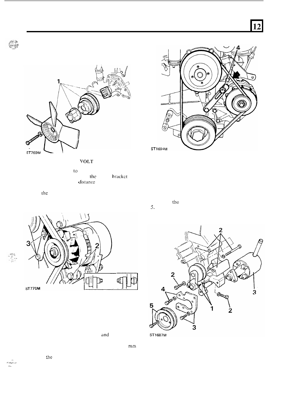
FIT ALTERNATOR
-
12
1.
Fit adjustment link
front cover.
2. Assemble the alternator to
engine
with
the two pivot bolts,
piece and washers,
leaving the bolts slack.
3. Fit
adjustment link to the timing cover and
attach
to
alternator
with
adjusting clamp bolt.
Adjust
belt tension
4.
Fit the drive belt and pivot the alternator away
from the engine, but do not apply pressure to the
stator
or slip-ring end bracket o r damage may
result. Tighten t h e clamp bolt
with thumb
pressure, check
t h e belt tension between the fan
and alternator pulleys which should be
7
to
9
at the mid-point.
5 .
When
tension is correct fully tighten the clamp
bolts and
the
pivot nuts and bolts.
.
.
FIT
PO WEK STEERING PUMP
1.
If removed, fit the jockey pullcy to the spindle.
2. Fit the bracket and jockey pulley assembly to the
3 . Fit the power steering pump to
t h e
bracket and
4.
Secure
plate to the bracket with the three bolts.
Fit the drive pulley
to the pump
with
the three
6. Fit the drive belt.
engine with the three bolts.
secure the plate to
t h e
pump with four bolts.
bolts.
91