Defender 90 / 110 / 130. Manual - part 35


  Index      Land Rover     Defender 90 / 110 / 130 - service repair manual


Search            


Content   ..  33  34  35  36   ..


Defender 90 / 110 / 130. Manual - part 35


2.50 

LITRE 

DIESEL ENGINE 

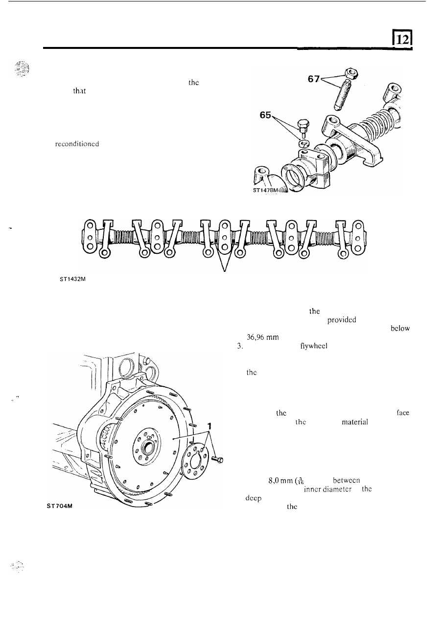
66.  Using  new  spacers  and  springs,  assemble  the 

rockers  and  brackets  to  the  shaft  as  illustrated, 

ensuring that  t h e  rockers move  freely on 

shaft. 

Note 

double spacers are fitted each side 

of 

the 

centre pedestal. 

67. 

Fit  the  tappet  adjustment  screws  and  lock  nuts  to 
the rockers. 

68.  Invert  the  rocker  assembly  and  locate 

it 

on  the 

rocker  cover  to  prevent 

it 

falling  apart.  Place  the 

cylinder  head  and  rocker  assembly 

to one side ready for fitting to the engine. 

66 

REMOVE 

AND 

OVERHAUL 

THE FLYWHEEL 

2.  Wear  or scores 

on 

flywheel  clutch  face can  be 

corrected  by  machining 

that  the  overall 

1. 

Remove  the flywheel  retaining  bolts and  withdraw 

width  of 

t h e  

flywheel  is  not  rcduccd 

Check  that  the 

has  not  been  previously 

the flywheel and reinforcing plate. 

(1.453 in). 

... 

machined. 

gcar can  be renewed. 

4. 

Examine the ring gear teeth and 

if 

chipped 

or worn 

Reface the flywheel 

5.  Remove the clutch location dowels. 
6 .   Machine 

flywheel over the complete clutch 

removing only 

minimum 

necessary  to 

achieve  a  smooth  flat  surface  parallel  with  the 
crankshaft  mating face and 

within 

the above width 

dimensions and 

fit 

new dowels. 

Renew 

the 

ring gear 

7.  Drill  a 

in) hole 

the root of  any 

two teeth and t h e  

of 

starter ring 

enough  to weaken  the ring. 

Do not  allow the 

drill to enter 

flywheel. 

59 

2.50 

LITRE DIESEL ENGINE 

8. 

Secure the flywheel 

in 

a soft jawed vice and cover it 

with  a  cloth 

to  protect  one  from  personal  injury. 

Place a cold chisel above the drilled hole and strike 

it 

sharply to split the ring gear. 

9. 

the 

ring  gear  uniformally  to  between 

and 

250°C  but  do  not  exceed  the  higher 

figure. 

10. 

Place 

flywheel,  clutch  face  down,  on  a  flat 

surface  and  locate  the  heated  flywheel 

with 

the 

square  cdge  of  teeth  downward  towards  the 

flywheel  clutch  face  and  chamfered  edge  of  the 
teeth uppermost. 

I .   Press the starter ring firmly against the flange until 

the  ring  contracts sufficiently  to grip  the  flywheel. 
Allow  the  ring  gear  to  cool  naturally. 

Do  not 

hasten cooling 

in anyway. 

10 

ST 

928M 

REMOVE AND OVERHAUL 

OIL PUMP 

Early type 

Remove the sump. 
Bend  back  the  lock  washers  and  remove  the  two 

bolts 

securing  the  oil  pump 

to  the  crankcase. 

Withdraw 

oil  pump complete 

with 

strainer and 

oil pump drive shaft. 

Dismantle 

oil 

pump 

3  Bend  back  the  lock 

and  release  the 

n u t  

securing  the  strainer  to  the 

pump  body  and 

remove the strainer and sealing ring. 

4. 

Remove  four bolts  and  washers and 

l i f t  

off  the  oil 

pump cover and 

lift 

out the driven and idler gears. 

(a) driven gear 
(b) 

gear 

60 

2.50 

LITRE 

DIESEL ENGINE 

-- 

5. 

Remove  t h e   oil 

sealing  washer.  Withdraw  the  relief  valve  spring, 
plunger and ball. 

pressure  relief  valve  plug  and 

NOTE: Later pumps have ten toothed gears and 

no 

relief valve ball. 

Overhaul the oil pump 

6. 

Examine the gears 

for wear, scores and  pits. If  the 

gears  appear  serviceable  check  for  end-float 

as 

fo  ws 

7.  Clean 

t h e  

pump  body  and  assemble  the  gears. 

Place a straight edge across 

pump body  face, as 

illustrated, and  using  a  feeler  gauge, measure  the 
clearance between the body  and gears. The correct 

clearances 

are 

as follows: 

8.  Idler gear 

to 0,015 

(0.003 to 0.006 in). 

9.  Driven gear 

to 

(0 002 to 0.005 in). 

10.  Gears  must  be  renewed 

in 

pairs. 

worn,  but 

serviceable gear,  must  not  be  matched 

with 

new 

one. 

11.  If  necessary renew idler gear spindle by  drilling-out 

the  peened  over  end  of  the  spindle  so  that 

t h e  

spindle can  be withdrawn  from the pump body. 

To 

ensure  squareness  w h e n   fitting  the  new  spindle, 
assemble 

it 

into 

t h e  

pump body  with  the two gears. 

Fit  the  cover  and  secure 

with 

four  bolts. 

Support  the  pump  body  and  peen  over  the  end 

of 

the  new spindle.  Remove the  cover and  gears and 

check security 

of  the spindle. 

12.  If  worn,  remove the idler gear bush  and  press in  a 

replacement.  Drill  the  lubrication  hole  3.17 
(0.125  in) and ream the bush  to 

in) 

diameter. 

..  . 

12 

13.  A  scored ball  valve  seat can be restored  by  using a 

locally  made  lapping tool  by  silver soldering a 

new 

ball  (part  number 

3748)  onto  a  length  of  suitable 

tube. 

14. 

Install  the  tube 

in  a  drill  and  lap-in  using 

grinding  paste.  Finally  hand-lap  the  seat 

with 

fine 

paste  using the same diabalo method 

as for lapping 

valves. 

15.  Thoroughly  wash  the  pump  body  to 

all 

traces of grinding paste. 

Assemble 

the 

oil 

pump 

i6.  Fit the 

gear to the 

17.  Fit  the  driven  gear  with  plain  part  of  the  bore 

uppermost. See illustration after instruction 

18.  Smear 

t h e  

joint  face  of  the  body 

with 

compound  and 

f i t  

the  cover  over  the  dowels 

the  strainer bracket  and secure 

with 

the  four  bolts 

and spring washers. 

19. 

Hold  relief  valve  bore  vertically  and  insert  the ball 
followed by  the plunger with  the ball seat end  first. 
Fit 

t h e  

spring, sealing washer and plug. 

Fit  the  oil  strainer  sealing  ring  to  the  pump  body 
followed  by  the  lock  washer  and  strainer. Tighten 
the  strainer  retaining  nut 

so  that  when  fitted  the 

strainer 

is  positioned  parallel  to  the 

baffle 

plate. Secure 

the 

n u t  

with  the lock washer  tab. 

Secure the  lower end  of  the bracket 

to 

the strainer 

with the single 

bolt, 

spring 

and 

plain washer. 

61 

2.50 

LITRE 

DIESEL ENGINE 

REMOVE 

OVERHAUL 

OIL 

Later 

Type 

Dismantle 

oil pump 

Remove the sump. 

2.  Bend  back  the  lock  washers  and  remove  the  two 

bolts  securing 

oil  pump 

to  the  crankcase. 

Withdraw  the oil  pump complete with  strainer and 
oil pump drive 

3. 

Bend  back  the  lock  washer  and  release  the  nut 

securing  the  strainer 

to  the 

oil  pump  body  and 

remove the strainer and scaling ring. 

4.  Remove 

four bolts  and  washers  and  lift  off  the oil 

pump cover and 

lift 

out the driven and idler gears. 

(a) 

gear 

(b) 

idler gear 

5 .  

Remove  the  oil  pressure  relief  valve  plug  and 

sealing  washer.  Withdraw  the  relief  valve  spring 
and plunger. 

Overhaul the oil pump 

6.  Examine  the gears for wear, scores and  pits. If  the 

gears  appear  serviceable  check 

far 

end-float 

as 

follows: 

7.  Clean  the  pump  body 

and 

the  gears. 

Place a straight edge across the pump body  face, as 
illustrated,  and  using  a  feeler  gauge,  measure  the 
clearance 

the body  and gears. The correct 

clearances  arc  given  in  the  Data  section 

05  book 

one. 

8.  Gears  must  be  renewed  in  pairs. 

worn,  but 

serviceable  gear, must  not  be  matched 

with 

a  new 

one. 

9.  If necessary renew idler gear spindle by  drilling-out 

the  peened  over  end  of  t h e   spindle  so  that  the 
spindle 

withdrawn 

from 

pump 

To 

ensure  squareness  when  fitting  the  new  spindle, 
assemble 

it 

into the pump body 

with 

two gears. 

Fit 

the  cover  and 

with  four  bolts.  Support 

t h e  

pump body  and  peen  over  the  end  of  the  new 

spindle.  Remove 

t h e  

cover  and  gears  and  check 

security of the spindle. 

continued 

62 


Content   ..  33  34  35  36   ..