Defender 90 / 110 / 130. Manual - part 32


  Index      Land Rover     Defender 90 / 110 / 130 - service repair manual


Search            


Content   ..  30  31  32  33   ..


Defender 90 / 110 / 130. Manual - part 32


2.5 

LITRE 

PETROL 

ENGINE 

Examine  the sprockets and discard 

if  the teeth  are 

8. 

Dismantle  the  tensioner  assembly  and  discard  if 

9. 

Examine the tensioner  body  and check that 

the oi! 

Examine 

slipper  and  check  that  the  oil  outlet 

11.  Check  that  t h e   oil  inlet  and  exit  oil  hole  in  the 

worn. 

any 

of  the parts are worn. 

inlet hole is clcar. 

hole is clear. 

tensioner mounting plate is clear. 

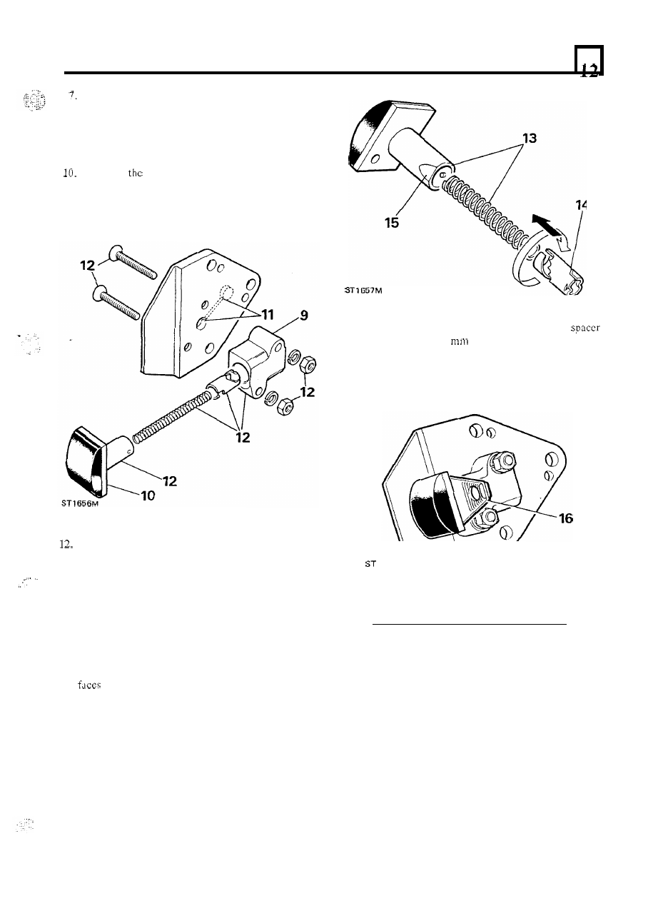
Assemble the tensioner 

body 

to the mounting plate 

with 

the  two socket  headed screws, spring washers 

and nuts. 

... 

13.  Insert the spring into the slipper bore. 
14. 

Fit  the  ratchet  over  the  spring  and  against  spring 

pressure,  insert  the ratchet  into the slipper bore  so 
that the groove 

in the ratchet locates over the small 

dowel  inside  t h e   slipper  bore.  Push  and  turn  the 
ratchet clockwise until it locks 

in 

the bore. 

15.  Insert 

the 

slipper assembly  into the tensioner 

b o d y  

ensuring  that  the  small  flat  on  the  slipper  shaft 

the mounting plate. 

16. 

To 

prevent  the tensioner  releasing,  insert 

approximately 

2.3 

thick  between  the  tensioner 

body 

and  back  of  the  slipper  prior  to  fitting 

to 

engine. 

662M 

47 

2.5 LITRE PETROL ENGINE 

VALVE TIMING 

6 .  

Fit  and  adjust  the  timing  chain  damper  so  that 

there  is  a  maximum  clearance 

of 

(0.010 in)  between  the  timing  chain  and  damper. 

Tighten 

retaining  bolts  and  secure  with  new 

lock tabs. 

Check that numbers one and four pistons are still at 

T.D.C.  and  without  disturbing  the  crankshaft, 
remove the pulley and timing cover. 

2. 

Fit 

the camshaft sprocket temporally and rotate the 

camshaft in  a  clockwise  direction  until  the  line  on 
the  tooth,  also  marked  with  a  letter 

is 

in  line 

with  the  top  stud  hole  on  the  cylinder  block  as 
illustrated. 

3. 

Remove the camshaft sprocket. 
Encircle  the  camshaft  and  crankshaft  sprockets 

with  the  timing  chain  and  keeping 

it 

taut  on  the 

drive  side  and  with  the  large  shoulder 

of  the 

crankshaft  sprocket  towards 

cylindcr block, 

fit 

the sprockets and chain assembly 

to the engine. 

5. 

Secure the camshaft sprocket 

to 

the camshaft  with 

a  new  special  micro  encapsulated  treated  bolt  and 
tighten to the correct torque figure. 

FIT TIMING CHAIN 

Fit 

t h e  

timing 

tensioner  and mounting platc 

assembly 

to 

t h e  

cylinder block  locating 

i t  

the 

two dowels. 

2.  Secure the assembly with 

three bolts and evenly 

tighten. 

3.  Remove  the spacer and  to release  the  ratchet,  to 

tension the chain, 

the pad at point ‘A’. 

. ... 

_.. 

.... 

.. 

2.5 

LITRE 

PETROL ENGINE 

RENEW EXHAUST VALVE SEAT INSERTS 

1. 

2. 

Hold  the  cylinder  head  firmly 

in  a  vice,  wear 

protective  goggles  and  grind  the  old  insert  away 
until  thin  enough  to  be  cracked  and  prised 

out. 

Take care not to damage the insert pocket. 

Remove  any  burrs  and  swarf  from  the  pocket. 

Failure  to  d o   this  could  cause  the  new  insert  to 
crack when being fitted. 

NOTE: Since no special  tool is available for fitting a 
new  insert,  it  is  recommended  that  this  work 

is 

entrusted 

to 

a cylinder head overhaul specialist. 

FITTING 

PISTONS AND CONNECTING RODS 

Fit rear main 

oil seal and flywheel housing 

2. 

3 .  

4. 

Check  that  the  crankshaft  oil  seal  journal  is 
undamaged  and clean.  Make sure the scal  housing 
is clean  and dry and free from  burrs. 

Do 

not  touch 

the seal  lip and 

that 

outside diameter is 

clean and dry. 
The 

seal Part 

N o  

ETC 

5369 

which  should 

be  used  is  supplied  with  a  former  to  maintain  the 

correct  shape  and 

must  not  be  removed  until  the 

seal 

is to be fitted. 

Using special 

seal 

18G 

1 and with the 

lip  side  leading drive-in  the  seal  as far 

as  the  tool 

allows. 

If  the tool is  not  available 

fit 

the 

seal 

to 

bottom of 

t h e  

housing to ensure 

The delection 

of  the oil spray hole 

in 

the connecting rod 

precludes  the  necessity 

of  fitting  this  towards  the 

camshaft side of  the engine. See page 18 instruction 

5. 

REMOVE AND 

FLYWHEEL  HOUSING AND 

REAR 

OIL SEAL 

1.  Remove  the  eight  bolts  securing  t h e   flywheel 

housing  to  the  cylinder  block  and  remove  the 
housing and rcar main  bcaring oil seal. 

842M 

699M 

2.5 

LITRE PETROL ENGINE 

5 .  

Apply  a bead 

of  Hylogrip 2000 sealant  to the  rear 

face 

of  t h e  flywheel  housing to the dimensions and 

configuration  as illustrated  below.  The illustration 
has been  produced  full  size 

so that  a template may 

be  made to facilitate the application  of  the sealant. 

The 

should  be 

wide  and 

thick. 

6.  Examine  the  seal  guide  number  18G  1344  and 

repair any damage that could destroy the seal lip. 

7.  Lubricate  the  outside  diameter  of  the  seal  guide 

and the scal journal  with concentrated  'Oildag'  in a 

25% 

solution with clean engine oil. 

8.  Place the seal guide on  the  crankshaft flange and, 

using  the two  dowels protruding  from  the cylinder 
block  rear  face  as  a  guide  to  ensure  initial 
squareness, 

fit 

the  flywheel  housing  and  remove 

the seal  guide.  Secure t h e  flywheel  housing  evenly 
tightening the retaining bolts. 

50 


Content   ..  30  31  32  33   ..