Defender 90 / 110 / 130. Manual - part 26
2.25
LITRE PETROL AND DIESEL ENGINE
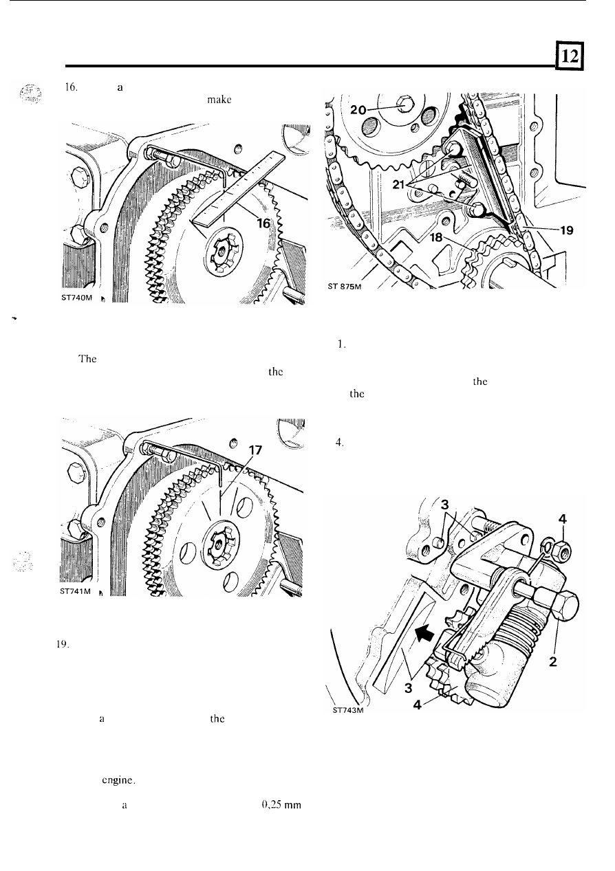
Using
rule, determine the exact mid-point
between the two marks and
a third mark.
..
17. Remove the dial indicator, and turn the camshaft
until the middle mark lines up with the pointer.
number one cylinder exhaust tappet roller
should now be resting
in
the centre of
four
degree flat period of the cam and the camshaft and
crankshaft
are
in
their correct relationship.
18.
Fit the crankshaft chain whee!
with
the large
shoulder towards the cylinder block.
Without moving the camshaft and crankshaft
fit
the
timing
chain keeping
i t
taut on the drive side.
Should
i t
be impossible to obtain a taut
fit,
remove
the chain wheel and position
i t
in one
of the five
remaining keyways until the best position is
obtained. It
is preferable
to choose
a
keyway which
gives slightly tight chain
on
drive side rather
than a slack one.
20.
Secure the camshaft chain wheel to the camshaft
with a new, special, micro encapsulated treated
bolt and tighten
to t h e
correct torque figure
-
See
Petrol
21.
Fit and adjust the timing chain damper so that
there is
maximum clearance of
(0.010
i n )
between the timing chain and damper.
Tighten the two bolts and secure
with
new lock
tabs.
.
...
FIT
TIMING
CHAIN TENSIONER
Assemble the timing chain tensioner
in accordance
with t h e illustration
in
“Dismantling”.
2. Compress the assembly against the spring and
fit
to
the engine whilst engaging
ratchet pivot
bolt in
cylinder block.
3 . Ensure that the piston housing locates on the
dowels and single stud and the cylinder spigot fits
into the milled slot
in the cylinder block.
Allow the jockey wheel
to take up the slack
in
the
chain. Tighten the retaining
n u t
and two bolts
to
secure t h e assembly.
Do not rotate enginc, see
‘tappet adjustment’.
23