Defender 90 / 110 / 130. Manual - part 24


  Index      Land Rover     Defender 90 / 110 / 130 - service repair manual


Search            


Content   ..  22  23  24  25   ..


Defender 90 / 110 / 130. Manual - part 24


... 

... 

. . 

...  . 

. . .  

.... 

2.25 

LITRE PETROL AND DIESEL ENGINE 

Assemble pistons 

to 

connecting-rods 

27.  Petrol  engine  pistons  can  be  fitted  either  way 

round, except  those that  are being refitted  to their 
original  bores 

in  which  case  they  must  be fitted  to 

the  connecting-rod  in  the  same  position  in 
accordance with the mark made during removal. 

28.  Inscrt  a circlip 

in 

side of  the gudgeon  pin  boss 

and assemble the piston  to 

connecting-rod  with 

t h e  

gudgeon  pin. Secure the assembly with a circlip 

on the opposite side of the piston. 

29.  Diesel  engine pistons  must  only  be  fitted  one way 

in  relation  to the connecting-rod. The piston  must 
be  assembled  with 

t h e   point 

of  the 

on  the 

piston  crown,  on  the same side 

as  the  lubrication 

hole in the connecting-rod.  Assemble  the piston  to 
the  connecting-rod 

in 

the same manner  as  for  the 

petrol engine. 
Place 

the 

piston  and  connecting-rod 

to 

one side ready 

for fitting to the cylinder block.  It  is 

good  practice  to  renew 

connecting-rod  bolts 

ASSEMBLE ENGINE 

FIT CRANKSHAFT 

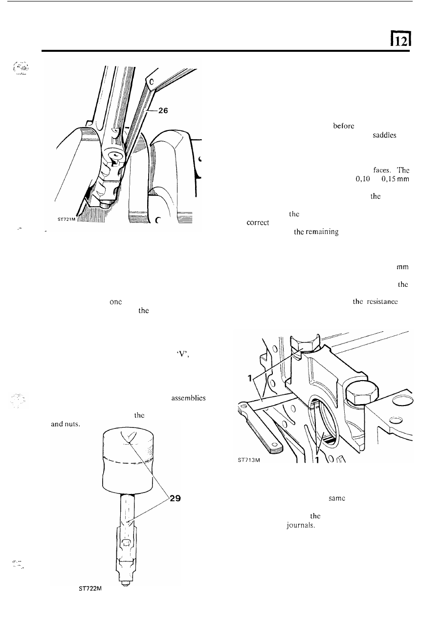
Main bearing nip and clearance 

New main bearing halves are supplied with a protective 
coating and must be degreased 

fitting. 

1. Fit the bearing  halves in  the crankcase 

and 

caps  and  secure  the  caps  to 

the  crankcase  and 

tighten 

to 

the correct torque.  Slacken the  bolts 

on 

one side 

of 

the caps only  and, with  a feeler gauge, 

check  t h e   gap  between  the  joint 
clearance 

or  nip  must  be  within 

to 

(0.004  to  0.006 in).  T h e   bearing  nip  can  be 
adjusted  by  selective  assembly  of 

bearing 

halves  available in varying thicknesses. 

Do not file 

or  machine 

caps  or  saddles 

to  achicvc  the 

clearance. Note that the rear main  bearings 

are wider than 

four. 

2.  T o  make a final check  that the clearance is  correct, 

leave  the  bearing  halves 

in  the  crankcase  saddles 

and  carefully  lower  the  crankshaft  into  position. 
Check each bearing 

in turn by inserting a 0,063 

(0.0025 in)  shim  paper  between  the  bearing  cap 
and crankshaft journal  and tighten  the  bolts  to 

correct  torque. 

If  the  clearance  is  correct,  there 

should  be 

a  slight  increase 

in 

to 

rotation  of  the crankshaft. 

As  an  alternative  ‘Plastigauge’  may 

bc  used  to 

check  the clearance 

in the 

manner 

as with  the 

connecting-rod  bearings. This material  may 

also be 

used  to  determine 

amount 

of  wear 

in 

used 

bearings and 

continued 

15 

2.25 

LITRE PETROL 

AND DIESEL ENGINE 

3.  Locate  the  crankshaft  in  position  on  the  upper 

5. 

Place  the  crankshaft 

in  position  in  the  crankcase 

bearing  halves  in  the  crankcase  and  wipe  any 

oil 

from  the  journals  since  ‘Plastigauge’ is  soluble  in 
oil.  Place  a piece  of  ‘Plastigauge’ across the  lower 
half  of  each  crankshaft  journal  o r   lower  bearing 

cap  shell. 

Fit 

the  cap  and  tighten 

to  the  correct 

torque. Remove the cap and bearing and using the 
scale  supplied  with  the  ‘Plastigauge’ measure  the 
flattened  ‘Plastigauge’  at  its  widest  point.  The 

graduation  that  most  closely  corresponds  with  the 
width 

of  the  ‘Plastigauge’  indicates  the  bearing 

clearance. 

The  correct  clearance  with  new  o r   overhauled 
components  is  included  in  “General  specification 
data”  section. If  new  bearings  are being  fitted  use 
selective assembly 

to obtain  the correct  clearance. 

Wipe off,  not  scrape the  ‘Plastigauge’ with  an  oily 
rag from the journals o r  bearings. 

and  mount  a dial  test  indicator to read-off  the end 

of 

the  crankshaft.  A  feeler  gauge  may  be  used 

instead 

of  an indicator. 

6. 

Determine the end-float  by  moving  the crankshaft 

away  from  the  indicator  and  zero  the  dial.  Move 
the  crankshaft  in  the  opposite  direction  and  notc 
the  indicator  reading.  Alternatively  measure  the 

clearance with  a feeler gauge. The end-float should 
be 

to 

(0.002 

t o  

0.006 in). 

7. 

If  adjustment  is  required  substitute  with  oversize 

thrust  washers.  Variation 

of 

thrust  washer 

thickness  at  each  side 

of  crankshaft  journal  must 

not  exceed 

(0.003 

in)  to  ensure  that  the 

crankshaft remains centralised. 

Adjust crankshaft 

end-float 

4.  Lift  out  the  crankshaft  and  insert  a  standard  size 

thrust washer both sides 

of fhe centre main bearing 

saddle with the grooves towards the crankshaft. 

engine 

oii  and 

fit 

the appropriate bearing caps and 

lower shells to the crankcase with  the exception 
number  five  main  bearing.  Ensure  that  the  caps 
locate  properly  over  the  dowels.  Using 
and  washers  evenly  tighten  t o   the  correct  torque 
figure. 

continued 

16 

2.25 LITRE 

PETROL AND DIESEL ENGINE 

10. 

To 

prevent  any  cork  seal  material  becoming 

trapped  between 

t h e  

bearing  cap  and  crankcase, 

chamfer  the  inner 

of  the  corks 

to 

to 

wide as illustrated. 

Immerse the cork seals 

in engine oil  and  fit them  to 

the bearing cap. 

.  . 

I .  

Fit  the bearing cap and lower shell to the crankcase 

and  secure with  new  bolts and washers and  tighten 
to the appropriate torque. 

12.  To allow  for  shrinkage after  fitting  leave 

t h e  

cork 

seais 

proud 

of  the crankcase-sump  face. If 

possible  delay  the  fitting  of  the  sump 

for 

approximately  twelve  hours  and  leave  the  seal 
protruding 

i n )   and 

then  place  a 

6,350 

in)  washer  over the  seal  and  cut  off 

the  surplus. 

If 

it 

is  necessary  to 

fit 

the  sump 

Fit rear main 

oil seal 

13.  Check  that  the  crankshaft  oil  seal  journal  is 

undamaged  and clean.  Make sure the seal  housing 
is  clean  and dry and 

from burrs. 

Do not  touch 

seal  lip and ensure that  the outside diameter is 

clean  and  dry. 

The 

P.T.F.E.  Seal  Part  N o   ETC 

5369  which  should  be  used,  is  supplied 

with 

former 

to 

maintain 

t h e  

correct  shape and  must  not 

be removed until the seal is 

to 

be 

fitted. 

14.  Using special seal replacer 

18G 134-1 1 and 

with 

the 

lip  side  leading  drive-in  the  scal  as  far  as  the  tool 

allows.  If  t h e  

tool is not 

fit 

the seal to the 

bottom  of  the housing 

to ensure squareness. 

17 

2.25 

LITRE PETROL AND 

DIESEL ENGINE 

15. 

Fit 

the 

'0' 

ring seal t o  the flywheel housing. 

16.  Examine 

seal  guide  number 

18G  1344  and 

repair any damage that could destroy the seal lip. 

17.  Lubricate  the  outside  diameter  of  the  seal  guide 

and the seal journal  with concentrated 'Oildag' 

i n  a 

solution 

with 

clean engine oil. 

18.  Place 

seal guide  on  the crankshaft  flange  and, 

using  the two  dowels protruding from  the cylinder 
block  rear  face  as  a  guide 

to  ensure  initial 

squareness, 

fit 

the  flywheel  housing  and  remove 

the seal guide. Secure the  flywheel  housing  evenly 
tightening 

the 

retaining bolts. 

5. 

Lubricate  the  cylinder  walls,  piston  rings  and 

suitable  compressor  tool  and  carefully  lower  the 
connecting-rod  into  the  bore  ensuring  that  the  oil 
spray  hole  faces  the  camshaft  side  of  the  engine. 
With  diesel  engines  the  point  of  the  arrow  headed 

valve  clearance  indentation 

in 

the  piston  crown, 

and  the oil  spray 

must  face  the 

side 

of the engine. 

6.  Using  a soft  mallet, sharply  tap 

piston  into the 

bore 

so  that  the  whole 

of  the  piston 

is 

just 

the surface of  the cylinder block. 

crankpins.  Compress  the  piston  rings 

with 

FIT THE CONNECTING-RODS AND PISTONS 

Turn  t h e  crankshaft 

to  position  numbers  one  and 

four  crankpins  at  bottom 

centre  to  facilitate 

fitting the connecting-rods. 

2. 

When  fitting  the  connecting-rods  and  pistons 
ensure 

that 

the  bolts  do  not 

foul  and  damage  the 

crankpins. 

As 

a precaution 

i t  

is recommended  that 

rubber 

or  soft  plastic  sleeves  are  placed  over  the 

threads. 

3 .   The  connecting-rod 

bolts 

have  eccentric  heads 

which  locate 

in 

a recess 

i n  the connecting-rod. I t  is 

the 

of  each 

new 

is 

located before tightening. 

4. 

Stagger the compression  rings 

so that  the gaps are 

equidistantly  spaced  round  the  piston  but, 

so 

arranged, 

that 

no  gap  is  positioned  on  the  thrust 

side  of  the  piston  i.e. opposite  the camshaft.  Turn 
the 

oil control ring so that the gap is 

in 

line with  the 

gudgeon pin. 

18 

7. 

Check  that  the  bearing  shell  is  properly  located 

in 

the  connecting-rod  and  pull  the  rod  onto  the 

crankpin. Locate 

t h e  

bearing shell correctly  and 

f i t  

the  cap 

so  that  the  identification  numbers  are 

together 

on the camshaft side of 

engine. 

Fit and 

tighten  new  nuts  to  the  correct  torque  figure. 
Repeat  the  foregoing  instructions 

for  fitting  the 

remaining piston and connecting-rod assemblies. 


Content   ..  22  23  24  25   ..