Defender 90 / 110 / 130. Manual - part 27
2.25 LITRE PETROL AND DIESEL ENGINE
FIT
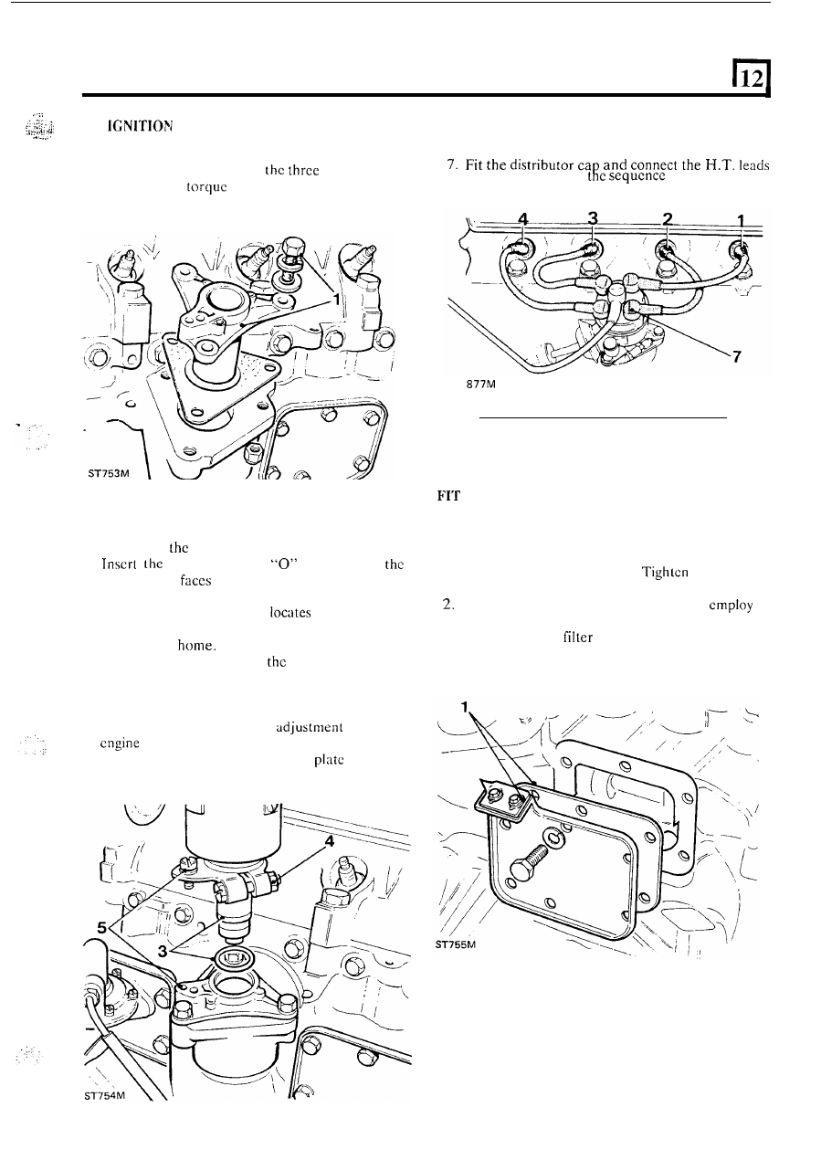
DISTRIBUTOR
6. Fit the correct spark plugs and washers and tighten
to the specified torque figure.
to the spark plugs
in
illustrated.
I .
Fit the distributor adaptor plate using a new joint
washer and evenly tighten
retaining bolts
to the correct
figure.
ST
F
UEL I
N
JEC
T
I
O
N
P
UMP
2. Chcck that the distributor drive coupling, locates
properly
in
off-sct
slot
of the skew gear.
3.
distributor and
ring
so that
vacuum
unit
towards
t h e
rear of the engine.
Remove the cap and oscillate the rotor arm until
the distributor drive shaft
into the drive
coupling
slot
thus enabling the distributor
to
be
pushed fully
The metal tip of the rotor arm
should be
in
line
with
electrode
in
the
distributor cap that supplies clcctrical current to
number one spark plug.
4.
Temporarily tighten the distributor clamp bolt
pending final ignition timing
when the
is fitted to the vehicle.
5.
Secure the clamp
to the adaptor
with
the
single bolt.
Using
timing gauge
605863
1.
Using a new joint washer fit the camshaft front side
cover with
t h e
timing pointer.
the retaining
bolts evenly to the correct torque.
Earlier engines with the side oil filter,
a
baffle plate,
with
two joint washcrs interposed
between the side
plate and the cylinder block.
continued
27