Defender (1999-2002). Manual - part 126


  Index      Land Rover     Defender - service manual 1999-2002 year


Search            


Content   ..  124  125  126  127   ..


Defender (1999-2002). Manual - part 126


86

ELECTRICAL

4

DESCRIPTION AND OPERATION

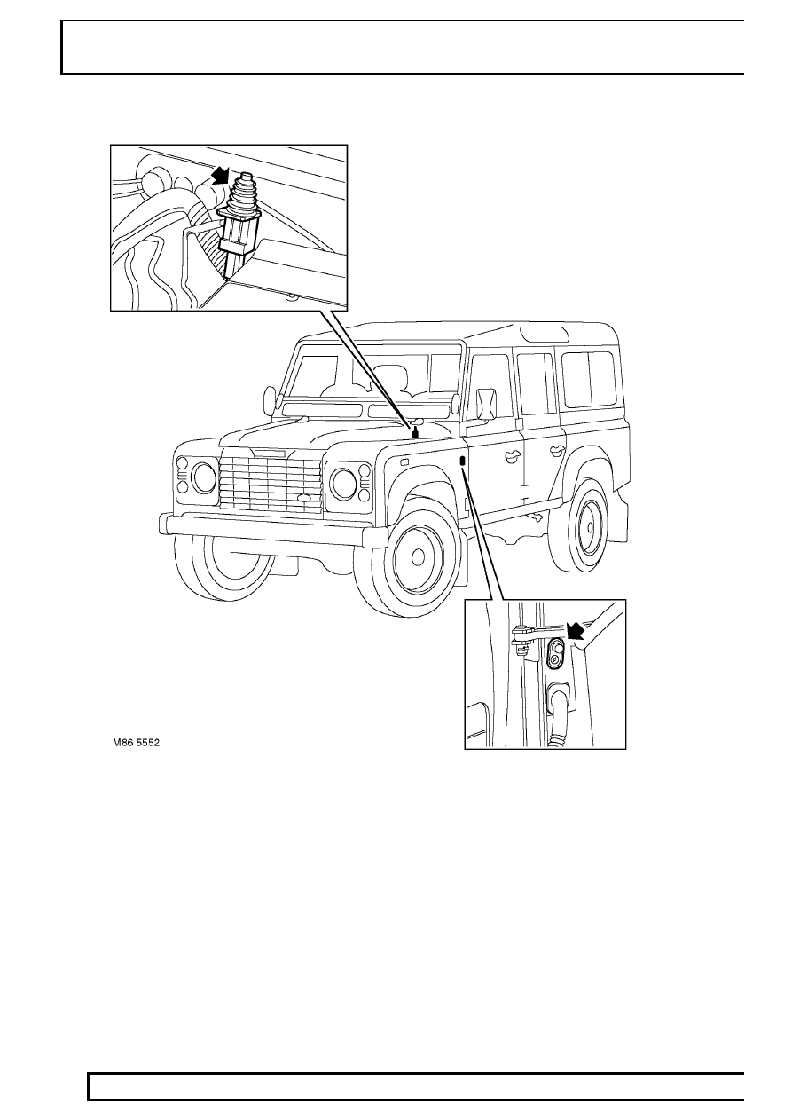
Door and Bonnet Switches

The bonnet switch is located at the rear of the bonnet aperture on the bulkhead. The door switches are located on
the ’A’ posts for the front doors, the ’B’ posts for the rear doors and on the inside face of the tail door aperture.

The drivers door switch and the bonnet switch are connected to the anti-theft alarm ECU on individual single
wires. The remaining passenger doors and, if applicable, the tail door are jointly connected on a single wire to the
ECU. If a fault occurs which involves incorrect mislock signals, alarm triggers and interior lamp operation, the door
switch earth may be the cause of incorrect operation.

If any door or the bonnet is opened, the switch closes and completes an earth path to the anti-theft alarm ECU.
This completed earth path input is sensed by the ECU, which, if armed, will sound the BBUS or alarm sounder.
The ECU also controls, via the door switches and ignition on/off signals, the operation of the interior lamps.

ELECTRICAL

5

DESCRIPTION AND OPERATION

Perimetric Protection

Perimetric protection is the monitoring of each opening door or bonnet to unauthorised intrusion. The anti-theft
alarm ECU uses the door and bonnet switches described previously to determine when illegal intrusion has
occurred.

If a door/bonnet is left open when the alarm system is armed, the ECU will determine a mislock situation which is
indicated by non operation of the hazard warning lamps. If the drivers door is left open, the security LED in the
instrument pack will be illuminated for the 10 second confirmation period. If any other door or the bonnet is left
open the security LED will remain off for the 10 second confirmation period. After the confirmation period, the LED
will revert to the 1Hz deterrent flash.

If the door/bonnetis subsequently closed, the hazard warning lamps will flash to show that full perimetric protection
is now invoked. The security LED will also resume the 10 second confirmation flash.

If only the bonnet is left open, all doors will have perimetric protection and volumetric protection will also be set. If
a door is left open, the volumetric protection is suspended until that door is subsequently closed.

Volumetric Protection

The vehicle alarm system can be armed with or without volumetric protection activated. If volumetric protection is
required, the vehicle must be locked using the lock button on the remote handset. If volumetric protection is not
required, because a pet is to be left in the vehicle for instance, the vehicle must be locked using the vehicle key in
the drivers door lock.

When the vehicle is locked using the remote handset, the volumetric sensor will wait for a period of 15 seconds
before arming. This allows time for the air in the vehicle to settle and prevent incorrect activation of the alarm.

If volumetric protection is set and there is a disturbance in the vehicle, i.e., a window left open or a moving object
in the vehicle, within the 15 second period, the volumetric sensor will not activate. The sensor must detect no
disturbance for the full 15 second period before arming.

86

ELECTRICAL

6

DESCRIPTION AND OPERATION

Volumetric Sensor

The volumetric sensor is located behind the RH ’B’ post on 90/110 station wagon models, on the headlining
between the interior lamp and rear view mirror on 90/110 pick-up models and on the headlining above the RH
door on 130 crewcab models.

The volumetric sensor operates by emitting a signal, which is received back to the sensor as it bounces back from
objects inside the vehicle. Once armed, the sensor will detect a disturbance to the returned waves. This is sensed
by the anti-theft alarm ECU which activates the alarm sounder or BBUS.

ELECTRICAL

7

DESCRIPTION AND OPERATION

Alarm Sounders

1. Battery Backed Up Sounder (BBUS)
2. Alarm sounder

Two types of alarm sounder are available, dependant on the vehicle market configuration.

A Battery Backed-Up Sounder (BBUS) is used in some markets and located in the LH front wing, behind the
headlamp. This is a tamper proof sounder with its own power supply which allows it to continue operating even if
disconnected from the vehicle power supply. The BBUS is connected to a permanent battery supply via fuse 7 in
the under seat fuse box. Two further connections are made to the anti-theft alarm ECU and a fourth connection is
to an earth header. If the BBUS is disconnected without first being disarmed by the anti-theft alarm ECU, it will
operate for 4.5 minutes.

To disarm the BBUS, when the battery is to be disconnected for instance, the ignition must be turned on to
position II and back to the off position , after which a 17 second delay is initiated to allow the battery or BBUS
connector to be disconnected. If the BBUS sounds, it can be disarmed by unlocking the vehicle with the remote
handset.

Where a BBUS is not specified, a standard vehicle horn is used for the alarm sounder and is located in the LH
front wing, behind the headlamp. The sounder is operated by an alarm relay which is controlled by the anti-theft
alarm ECU. The relay receives a permanent battery supply via fusible link 6 in the under seat fuse box. The relay
coil is connected to the anti-theft alarm ECU which provides an earth for the coil when horn operation is required.
This operates the relay contacts and supplies battery voltage to the sounder, causing it to operate.


Content   ..  124  125  126  127   ..