Defender (1999-2002). Manual - part 76


  Index      Land Rover     Defender - service manual 1999-2002 year


Search            


Content   ..  74  75  76  77   ..


Defender (1999-2002). Manual - part 76


MANUAL GEARBOX

1

ADJUSTMENT

SPRINGS - GEAR LEVER BIAS

Service repair no - 37.16.26

Check

NOTE: The purpose of this adjustment is
to set both bolts so that the bias spring
legs apply equal pressure on both ends of

the gear lever cross pin when 3rd or 4th gear is
engaged. This will ensure that when the gear lever
is in neutral, the gear change mechanism is
automatically aligned for 3rd or 4th gears.

1. Remove gear lever knobs.
2. Release and remove gear lever gaiter.
3. Select 3rd or 4th gear.

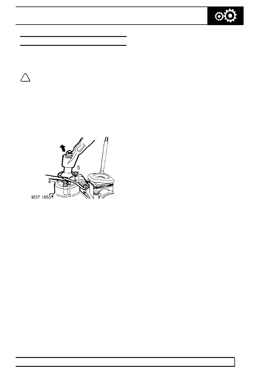
4. Adjust the two adjusting screws until both legs of

the spring are approximately 0.5 mm (0.02 in)
clear of cross pin in the gear lever.

5. Apply a light load to the gear lever in a RH

direction and adjust the LH adjusting screw
downwards until the LH spring leg just makes
contact with the cross pin.

6. Repeat the same procedure for the RH adjusting

screw.

7. Lower both adjusting screws equal amounts until

the radial play is just eliminated. Tighten lock
nuts.

8. Return gear lever to neutral position and move

gear lever across the gate several times. The
gear lever should return to the 3rd and 4th gate.

9. Fit gear lever gaiter.

10. Fit gear lever knobs.

37

MANUAL GEARBOX

2

ADJUSTMENT

GEARBOX OIL - DRAIN AND REFILL

Service repair no - 37.24.01

Drain

1. The oil should be drained when the gearbox is

warm and the vehicle is standing on a level
surface.

WARNING: Observe due care when
draining gearbox as oil can be very hot.

2. Raise vehicle on ramp.
3. Position container to collect oil.
4. Clean area around filler/level plug.

5. Remove filler/level plug.

NOTE: Later gearboxes: Use No. 55 Torx
bit to remove filler/level plug.

6. Remove gearbox drain plug and discard sealing

washer.

Refill

1. Clean gearbox drain plug and fit new sealing

washer.

2. Fit gearbox drain plug and tighten to 50 Nm (36

lbf.ft).

3. Fill gearbox with correct grade of oil. See

LUBRICANTS, FLUIDS AND CAPACITIES,
Information.

4. Apply Loctite 290 to the filler/level plug and

tighten to 30 Nm (22 lbf.ft).

5. Remove fluid container.
6. Lower vehicle on ramp.

MANUAL GEARBOX

1

REPAIR

COVER - FRONT - RESEAL AND FIT NEW INPUT
SHAFT OIL SEAL

Service repair no - 37.12.33.01

Remove

1. Remove gearbox. See this Section.

2. Remove retaining peg and remove release

bearing.

3. Remove bolt securing clutch release fork,

remove retaining clip and remove clutch release
fork.

4. Remove 2 bolts securing release bearing sleeve,

remove bearing sleeve.

5. Remove 6 bolts securing clutch housing, remove

housing.

6. Remove and discard 6 bolts securing front

cover, remove cover.

37

MANUAL GEARBOX

2

REPAIR

7. Using a soft metal drift, carefully remove input

shaft front bearing track from front cover.

CAUTION: Take care not to damage
bearing track, if track is damaged, it will be
necessary to fit a new input shaft front

bearing.

8. Remove input shaft oil seal from front cover;

discard oil seal.

Refit

9. Using a suitable solvent clean seal recess, front

cover and gearbox mating faces; clean threads
of bolts and bolt holes.

10. Clean bearings and bearing races.
11. Lubricate a new oil seal with gearbox oil.
12. Fit oil seal using a suitable mandrel.
13. Fit input shaft front bearing track using a press

and suitable mandrel.

14. Apply sealant, Part No. STC 4404 to front cover.
15. Position front cover, apply Loctite 290 to threads

of bolts; fit new bolts and tighten by diagonal
selection to 25 Nm (18 lbf.ft).

16. Clean clutch housing mating faces, dowels and

dowel holes.

17. Position clutch housing, fit bolts and tighten by

diagonal selection to 75 Nm (55 lbf.ft).

18. Clean bearing sleeve mating faces, dowel and

dowel holes.

19. Position bearing sleeve, fit bolts and tighten to

25 Nm (18 lbf.ft).

20. Examine clutch release fork pivot points for wear

and replace as required.

21. Apply a smear of Molybdenum disulphide grease

to pivot points and position release fork.

22. Fit retaining clip ensuring it locates over pivot

point washer, fit bolt and tighten to 10 Nm (7
lbf.ft).

23. Clean release bearing and bearing sleeve

mating faces.

24. Apply smear of Molybdenum disulphide grease

to release bearing sleeve.

25. Fit release bearing and secure with retaining

peg.

26. Fit gearbox. See this Section.


Content   ..  74  75  76  77   ..