Defender (1999-2002). Manual - part 64


  Index      Land Rover     Defender - service manual 1999-2002 year


Search            


Content   ..  62  63  64  65   ..


Defender (1999-2002). Manual - part 64


19

FUEL SYSTEM

14

REPAIR

Refit

19. Clean fuel pump and mating face.
20. Fit new fuel pump sealing ring.
21. Fit fuel pump and secure with locking ring.
22. Fit breather hose and secure clip.
23. Position heat shield and secure with scrivits.
24. With assistance position fuel tank and support

plate.

25. Connect fuel hoses and multiplug to fuel pump.
26. Connect filler neck breather and secure clip.
27. Position vent hose and secure to chassis clips.
28. Raise fuel tank to its fitted position.
29. Fit nuts and bolts securing fuel tank and tighten

to 25 Nm (18 lbf.ft) .

30. Connect filler hose and secure clip.

Vehicles fitted with tow bar

31. Position support bar and tighten nuts and bolts.
32. Reconnect battery negative lead.
33. Fit battery cover.

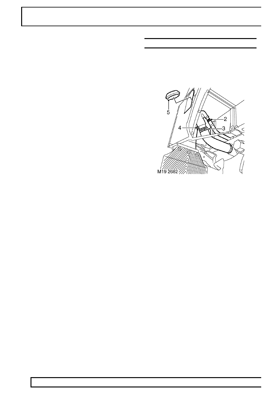
NECK - FUEL TANK FILLER

Service repair no - 19.55.07

Remove

1. Drain fuel tank. See Adjustment.

2. Loosen clip securing breather hose to fuel filler

neck and release hose.

3. Loosen clip securing fuel filler hose to neck and

release hose.

4. Remove screw and release earth lead from filler

neck.

5. Remove grommet securing filler neck to body.
6. Remove filler neck from body.

Refit

7. Fit filler neck to body.
8. Coat rubber grommet with soap solution.
9. Fit rubber grommet securing filler neck to body.

10. Connect earth lead and tighten screw.
11. Connect filler hose to neck and tighten clip.
12. Fit breather hose to filler neck and secure with

clip.

26 - COOLING SYSTEM

CONTENTS

Page

DESCRIPTION AND OPERATION

COOLING SYSTEM COMPONENT LAYOUT

2

.....................................................

COOLING SYSTEM COOLANT FLOW

4

...............................................................

GENERAL

5

............................................................................................................

OPERATION

11

......................................................................................................

ADJUSTMENT

DRAIN AND REFILL

1

............................................................................................

REPAIR

COUPLING - COOLING FAN

1

...............................................................................

THERMOSTAT

1

.....................................................................................................

PUMP - COOLANT

2

..............................................................................................

RADIATOR

3

...........................................................................................................

26

COOLING SYSTEM

2

DESCRIPTION AND OPERATION

COOLING SYSTEM COMPONENT LAYOUT

COOLING SYSTEM

3

DESCRIPTION AND OPERATION

NOTE: Inset A shows differences for Pre
EU3 models

1. Pressure cap
2. Overflow pipe
3. Heater return hose
4. Heater matrix
5. Heater inlet hose
6. Oil cooler return pipe - EU3 models
7. Connecting hose
8. Oil cooler housing assembly
9. Heater inlet pipe

10. Connecting hose
11. Outlet housing
12. Engine Coolant Temperature (ECT) sensor
13. Bleed screw
14. Radiator top hose
15. Radiator - upper
16. Intercooler
17. Gearbox oil cooler
18. Radiator - lower
19. Viscous fan
20. Drain plug
21. Connecting hose
22. Fuel cooler feed hose
23. Radiator bottom hose
24. Thermostat housing
25. Connecting hose
26. Coolant pump feed pipe
27. Coolant by-pass pipe
28. Radiator bleed pipe
29. Connecting hose
30. Coolant pump
31. Fuel cooler
32. Heater/expansion tank return hose
33. Expansion tank
34. EGR Cooler - EU3 models
35. Connecting hose - EU3 models
36. Connecting hose - EU3 models
37. Hose - EGR Cooler to oil cooler return pipe -

EU3 models

38. Radiator lower feed hose - Pre EU3 models
39. Oil cooler return pipe - Pre EU3 models


Content   ..  62  63  64  65   ..