Defender (1999-2002). Manual - part 25


  Index      Land Rover     Defender - service manual 1999-2002 year


Search            


Content   ..  23  24  25  26   ..


Defender (1999-2002). Manual - part 25


ENGINE

29

DESCRIPTION AND OPERATION

Timing chain guides

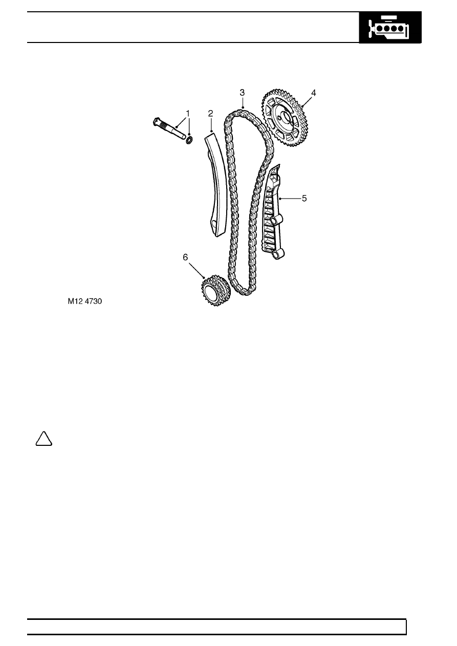
1. Hydraulic tensioner
2. Adjustable tensioner arm
3. Duplex timing chain

4. Camshaft sprocket
5. Fixed tensioner arm
6. Crankshaft sprocket

The crankshaft sprocket to camshaft sprocket timing chain is held taut by a tensioner arm acting on the slack side
of the chain. The tensioner is automatically adjusted by means of an hydraulically operated tensioner adjuster.
The drive side of the chain has a plastic guide attached to the front face of the cylinder block. The fixed guide is
attached to the front of the engine block by two bolts. The tensioner arm is fixed to the front of the cylinder block
by a single pivot bolt which allows the tensioner arm to pivot about its axis.

NOTE: The adjustable tensioner arm is not interchangeable between pre-EU3 and EU3 vehicles
due to a change in geometry on the EU3 version.

12

ENGINE

30

DESCRIPTION AND OPERATION

CAMSHAFT COVER COMPONENTS

The camshaft cover cover components are described below:

Camshaft cover
The camshaft cover is cast from aluminium alloy and is fixed to the camshaft carrier / cylinder head assembly by
thirteen bolts. The cover has spacers and sealing washers inserted into each of the thirteen bolt holes.

A breather hose is connected to a port at the top of the camshaft cover by means of a hose clip which vents
crankcase gases back to the air intake via a breather valve in the air intake tract, located forward of the
turbocharger in the flexible air intake duct.

A rubber seal is fitted between the camshaft cover and camshaft carrier.

An oil filler aperture is included in the top of the camshaft cover, which is sealed with a plastic cap with integral
rubber seal.

CAMSHAFT TIMING CHAIN COMPONENTS

The timing chain cover and timing chain components are described below:

Timing chain cover
The timing chain cover is cast and machined aluminium alloy and is attached to the cylinder head by a bolt at the
RH top of the cover and by a stud and nut at the LH top of the cover. Eight screws are used to attach the timing
chain cover to the front of the engine block. The timing cover is located to the cylinder block front face by two
dowels.

A viscous fan is attached to an idler pulley at the front of the engine block. The fan bearing is located on a shaft
and held in place by a circlip and a bearing flange, the inner race of the fan bearing is an interference fit on the
shaft. The fan idler pulley is attached to the bearing hub by three bolts and the fan itself is secured to the pulley
and bearing shaft by a left-hand threaded nut.

The front of the crankshaft passes through a hole in the lower part of the timing cover. An oil seal is pressed into a
recess in the front of the timing cover to seal the interface between the front of the crankshaft and the timing
cover.

A stub pipe is fitted to the front RH side of the timing cover which is used to attach the oil drain pipe from the
vacuum pump by means of a hose and spring clip.

Timing chains
The timing chain between the camshaft and crankshaft sprockets is a duplex type, each chain having 56 links.
The timing chain is contained between a fixed plastic guide and an hydraulically adjustable plastic tensioner arm
which are attached to the front of the engine block.

To cope with the higher injection loads of the EU3 engine, the timing drive between the camshaft and crankshaft
has been upgraded. This requires thicker chain links to be used, therefore the individual pre EU3 and EU3
components are not interchangeable.

To distinguish between the two timing chains the links are different colours. A pre EU3 chain has blue links. An
EU3 chain has bronze links.

The oil pump timing chain is a single type and traverses the oil pump sprocket and the rear crankshaft sprocket.

The timing chains are oil lubricated, with oil being provided by a chain lubrication jet and from oil flow returning
back to the sump from the cylinder head. An oil hole is included at the front left hand side of the cylinder head
which supplies oil from the cylinder head oil galleries.

ENGINE

31

DESCRIPTION AND OPERATION

Tensioner adjuster

1. Oil supply hole
2. Tensioner adjuster body

3. Tensioner adjuster plunger
4. Sealing ring

The tensioner adjuster is hydraulically operated, oil enters the adjuster from the pressurised oil supply flowing
through the cylinder head to operate a plunger which pushes against a pivoting plastic tensioner arm. The lateral
movement in the tensioner arm causes the timing chain to tension and consequently compensation for chain
flutter and timing chain wear is automatically controlled. The adjuster is located at the front right hand side of the
cylinder head, just above the timing chain cover and below the vacuum pump oil feed port. The adjuster body is
threaded and screws into a tapping in the cylinder head. Holes are contained in the adjuster body to receive oil
from the cylinder head galleries, the oil pressure is used to force the plunger out of the adjuster body to press the
tensioner arm against the timing chain and so using the oil trapped in the adjuster body to act as a damper.

The internal damping of the hydraulic tensioner is tuned for each application. This means that pre-EU3 and EU3
components are not interchangeable.

Drive train sprockets
The camshaft sprocket has a double row of teeth which locate with the duplex timing chain. The sprocket is fitted
to the camshaft by three bolts.

The oil pump sprocket is located on the front of the oil pump housing by a single retaining bolt. The sprocket has a
single row of teeth which locates with the oil pump drive chain.

The crankshaft sprocket contains three rows of teeth, the rear row locates on the single oil pump chain and the
front two rows locate with the duplex timing chain. The crankshaft sprocket has a slot in its internal diameter which
locates with the Woodruff key on the crankshaft. The front of the crankshaft sprocket has a timing mark.

As a consequence of thicker chain links being used on EU3 vehicles, the thickness of the camshaft and crankshaft
sprocket teeth has been reduced. Individual pre-EU3 and EU3 components are therefore not interchangeable.

12

ENGINE

32

DESCRIPTION AND OPERATION

CYLINDER BLOCK FLOW


Content   ..  23  24  25  26   ..