Defender (1993+). Manual - part 98


  Index      Land Rover     Defender - service manual 1993 year


Search            


Content   ..  96  97  98  99   ..


Defender (1993+). Manual - part 98


ELECTRICAL EQUIPMENT 

DISTRIBUTOR - LUCAS 35DLM8 

Overhaul 

16.  Renew  pick-up  and  base  plate  assembly  if 

module is  known to  be faulty,  otherwise check 
pick-up winding resistance (2k-5k ohm). 

DISTRIBUTOR COVER 

RE-ASSEMBLY 

1. 

Unclip and remove the cover. 

17.  This  is  mainly  a  reversal  of  the  dismantling 

2. 

Renew the cover if known to  be faulty. 

3. 

Clean the cover  and 

HT 

brush with a nap free 

cloth. 

LUBRICATION 

procedure, noting the following  points: 

ROTOR  ARM 

Apply  clean engine oil: 

4.  Pull rotor arm from  keyed shaft. 
5. 

Renew rotor arm if  known to  be faulty. 

a.  Three drops to felt  pad reservoir in rotor shaft. 

Apply Chevron SR1  (or equivalent) grease. 

INSULATION COVER (Flash shield) 

b.  Auto advance mechanism. 

d.  Pre  tilt  spring  and  its  rubbing  area  (pick-up 

and base plate assy). 

VACUUM UNIT 

e.  Vacuum  unit  connecting  peg  (pick-up  and 

base plate assy) and 

8.  Remove  two  screws  from  vacuum  unit 

f. 

the  connecting  peg  hole  in  vacuum  unit 

6.  Remove cover, secured by three screws. 

c.  Pick-up plate centre bearing. 

7. 

Renew cover if  known to be faulty. 

securing  bracket,  disengage  vacuum  unit 

connecting rod. 

connecting  rod  from  pick-up  base  plate 
connecting  peg,  and  withdraw  vacuum  unit 

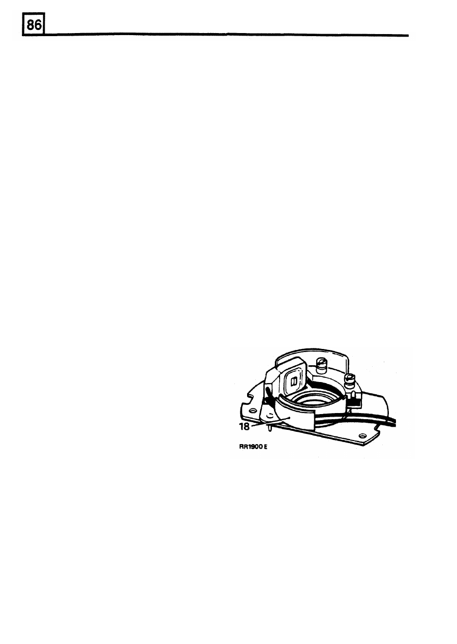
FITTING PICK-UP AND  BASE PLATE ASSEMBLY 

from distributor  body. 

18.  Pick-up  leads  must  be  prevented from  fouling 

AMPLIFIER  MODULE 

the  rotating  reluctor.  Both  leads  should  be 
located 

in 

plastic  carrier  as  illustrated.  Check 

9.  Remove two screws and withdraw  the module. 

during re-assembly. 

10.  Remove the gasket. 
11. 

Remove  two  screws  securing  the  cast 
heatsink and remove the heatsink. 

WARNING:  The  amplifier  contains  Beryllia. 

Do 

not open or crush. 

PICK-UP AND  BASE PLATE ASSEMBLY 

12.  Use  circlip  pliers  to  remove  the  circlip 

retaining the reluctor on rotor shaft. 

13. 

Remove  the flat  washer  and then the ' O '  ring 
recessed in the top  of  the reluctor. 

14.  Gently  withdraw  the  reluctor  from  the  shaft, 

taking care not 

to 

damage the teeth. 

REFlTTlNG RELUCTOR 

19.  Slide reluctor as far  as 

it 

will go on rotor  shaft, 

then  rotate  reluctor  until  it  engages  with  the 
coupling ring  beneath the  pick-up  base  plate. 
The distributor shaft, coupling ring and reluctor 
are  'keyed'  and  rotate  together.  Fit  the  'O' 
ring, flat washer  and retaining circlip. 

NOTE: Coupling ring fitted  beneath reluctor. 

15.  Remove  three  support  pillars  and  cable 

grommet.  Lift  out  the  pick-up  and  base  plate 
assembly. 

NOTE: 

Do 

not  disturb  the  two  barrel  nuts 

securing  the  pick-up  module,  otherwise  the  air 
gap will  need re-adjustment. 

REISSUED: FEB 1993 

ELECTRICAL EQUIPMENT 

compression stroke. 

PICK-UP AIR GAP ADJUSTMENT 

2.  Turn  distributor  drive  until  rotor  arm 

IS 

approximately 30°  anti-clockwise  from  number 
one  sparking plug lead position on cap. 

20.  The  air  gap  between  the  pick-up  limb  and 

reluctor  teeth  must  be  set  within the  specified 
limits, using a non-ferrous feeler  gauge. 

21.  If  adjustment  is  necessary,  slacken  the  two 

barrel  nuts  to  set  the  air  gap.  See  Engine 

Tuning Data. 

3. 

Fit distributor to engine. 

4.  Check that centre  line  of  rotor  arm  is  now 

in 

line  with  number one  sparking  plug  lead  on 
cap.  Reposition distributor if  necessary. 

5.  If  distributor  does  not  seat  correctly  in  front 

drive  is  not  engaged.  Engage 

sing  down  distributor  while 

turning engine. 

6.  Fit  clamp  and  bolt  leaving  both  loose  at  this 

stage. 

7 .  

Connect the vacuum pipe to the distributor. 

8.  Fit low tension lead to  coil. 
9. 

Fit distributor cap. 

10. 

Reconnect the battery. 

11. 

Using  suitable  electronic  equipment  set  the 
ignition timing dynamically. 

Dynamic ignition timing 

Equipment  required 

Calibrated Tachometer 
Stroboscopic  lamp 

NOTE:  When  the original  pick-up and  base plate 

assembly has been refitted the air 

gap 

should be 

checked,  and adjusted if necessary. 

1. 

Couple 

stroboscopic 

timing 

lamp 

and 

tachometer 

to 

engine 

following 

the 

When  renewing  the  assembly  the  air  gap  will 

manufacturers instructions. 

require adjusting to within the specified 

limits. 

2. 

Disconnect  the  vacuum  pipes  from  the 
distributor. 

AMPLIFIER  MODULE 

3.  Start  engine, with  no  load  and  not  exceeding 

3,000 

rev/min,  run  engine  until  normal 

22.  Before fitting  the  module,  apply  MS4  Silicone 

operating temperature is reached. (Thermostat 

grease 

or 

equivalent  heat  -  conducting 

open).  Check  that  the  normal  idling  speed 

compound to  the  amplifier  module  backplate, 

falls  within  the  tolerance  specified  in  the  data 

the  seating face  on  distributor  body  and  both 

section. 

faces of the heatsink casting. 

4. 

Idle  speed  for  timing  purposes  must  not 

exceed  750  rpm,  and  this  speed  should  be 
achieved  by  removing  a  breather  hose  NOT 

BY ADJUSTING IDLE SETTING SCREWS 

1. 

It 

is  essential  that  the  following  procedures 

5. 

With  the  distributor  clamping  bolt  slackened 

are  adhered to.  Inaccurate timing  can  lead to 

turn  distributor  until  the  timing  flash  coincides 

serious engine damage and additionally create 

with  the  timing  pointer  and  the  correct  timing 

failure to  comply with the  emission regulations 

mark  on  the  rim  of  the  torsional  vibration 

applying  to  the  country  of  destination.  If  the 

damper  as  shown  in  the  engine  tuning 

engine  is  being checked in the  vehicle  and 

is 

section. 

fitted  with  an  air  conditioning  unit  the 

6. 

Retighten 

the 

distributor 

clamping 

bolt 

compressor  must be isolated. 

securely.  Recheck  timing  in  the  event  that 

2. 

On initial engine build,  or  if  the  distributor has 

retightening  has  disturbed  the  distributor 

been  disturbed  for  any  reason,  the  ignition 

position. 

timing  must be set statically to 6° B.T.D.C. 

IGNITION TIMING ADJUSTMENT 

7. 

Refit vacuum pipes. 

(This  sequence  is  to  give  only  an  approximation in 

8. 

Disconnect  stroboscopic  timing  lamp  and 

order  that  the  engine  may  be  started)  ON  NO 
ACCOUNT  MUST  THE  ENGINE  BE  STARTED 

BEFORE THIS OPERATION IS CARRIED OUT 

Static ignition timing 

tachometer from engine. 

1. 

Set engine  -  No.  1  piston  to  6° B.T.D.C.  on 

REISSUED: 

FEB 

1993 

ELECTRICAL EQUIPMENT 

ELECTRONIC IGNITION - PRELIMINARY CHECKS 

EXPECTED READINGS 

Inspect  battery  cables  and  connections  to  ensure 

they  are  clean  and  tight.  Check  battery  state 

of 

charge if  in doubt  as  to  its condition. 
Inspect  all  LT  connections  to  ensure  that  they  are 
clean  and  tight.  Check  the 

HT 

leads  are  correctly 

positioned  and  not  shorting  to  earth  against  any 
engine  components.  The  wiring  harness  and 
individual cables  should be firmly  fastened to  prevent 

chafing. 

V1. 

More than  11.5 volts 

V2. 

volt  max  below volts  at  point 

in 

test  circuit 

V3. 

volt  max  below volts at point 

in test  circuit 

V4.  0 volt  0.1  volt 

PICK-UP AIR  GAP 

Check air  gap with  a non-ferrous feeler  gauge. 

NOTE: The  gap  is  set  initially  at  the  factory  and 
will  only  require  adjusting  if  tampered  with  or 
when  the  pick-up module 

is 

replaced. 

TEST  1: 

Check HT Sparking 

Remove coil/distributor 

HT 

lead from distributor cover 

and hold approximately 6 mm from  the engine block. 
Switch the ignition 'on'  and operate the starter. 
If 

regular  sparking  occurs,  proceed to  Test  6.  If 

no 

sparking proceed to Test 

2. 

(c)  If all readings are correct proceed to Test  3. 

(d)  Check  incorrect  reading(s)  with  chart  to 

identify area  of  possible faults,  i.e.  faults listed 
under  heading 'Suspect'. 

(e)  If  coil  or  amplifier  is suspected,  disconnect LT 

lead  at  coil,  repeat  V3.  If  voltage  is  still 
incorrect, fit  new coil. If voltage is now correct, 

check 

LT 

lead, if satisfactory 

fit 

new amplifier. 

(f)  If engine will  not start proceed to Test 3. 

KEY 

O K   Expected Voltage. 
H  Voltage higher than expected. 

L  Voltage lower than expected. 

TEST 3: 

Check Amplifier  Switching 

Connect the  voltmeter  between battery positive (-ve) 
terminal  and 

HT 

coil  negative  (-  ve)  terminal:  the 

voltmeter should register zero volts. 

Switch  the  ignition 

'on' 

and  crank  the  engine.  The 

voltmeter  reading should increase just  above zero,  in 
which case proceed with Test 

5. 

TEST 

2: 

L.T. 

Voltage 

Switch the ignition 

'ON' 

(a)  Connect  voltmeter  to  points  in  the  circuit 

indicated  by  the  arrow  heads  and  make  a 
note of  the voltage readings. 

(b)  Compare voltages  obtained with  the  specified 

values listed below: 

REISSUED: 

FEB 

1993 

ELECTRICAL 

EQUIPMENT 

If 

there  is  no  increase  in  voltage  during  cranking 

proceed to Test 4. 

TEST 5: 

Coil 

HT Sparking 

Remove  existing  coil/distributor  HT  lead  and  fit  test 
HT  lead to  coil tower. Using suitable  insulated pliers, 
hold free end about 6 mm from  the engine block  and 

crank the engine. There should be 

good HT spark. 

If weak  or  no sparking, 

fit 

new coil,  repeat test. 

HT  sparking  good,  repeat  test  with  original  HT  lead. 
If sparking is good, carry out Test 6. 

If 

weak or no  sparking,  fit  new HT  lead,  if  engine will 

not start carry out 

Test 

TEST 4: 

Pick-Up Coil Resistance. 

Disconnect  the  pick-up  leads  at  the  harness 

connector.  Connect  the  ohmmeter  leads  to  the  two 
pick-up leads in the plug. 

The  ohmmeter  should  register  between  2k  and  5k 
ohms  if  pick-up  is  satisfactory.  If  the  ohmmeter 
reading  is  correct,  check  all  connections  between 
pick-up  and amplifier,  if satisfactory, fit  new amplifier. 

If the engine still does not start carry out Test  5. 

Change the  pick-up if ohmmeter reading is incorrect. 
If 

the engine still  does not start proceed to Test 

5. 

TEST 

6: 

Rotor 

Arm 

Remove  distributor  cover.  Disconnect  coil  HT  lead 

from  cover  and  using  insulated pliers,  hold  about  3 

mm above rotor arm electrode and crank  the engine. 

There  should  be  no  HT  sparking between  rotor  and 

HT lead. 

If 

satisfactory carry out Test 7 .  

If  HT sparking occurs, an earth fault  on the rotor arm 

is indicated. Fit new rotor arm. 

If engine will  not  start carry out Test 7 .  

REISSUED: 

FEB 1993 


Content   ..  96  97  98  99   ..